In an earlier post, we had done a front brake pads change in the Miata, but while doing that change realized that one of the bolts slipped because the threading in the calipers was damaged. So we ended up doing a complete front and rear caliper replacement using remanufactured stock calipers from RockAuto. The good thing about these new calipers was that they were painted red which would look great on our car. In this post, we demonstrate how to go about removing and installing calipers. This work was done in August 2020, but we only found time a year later to write this post. I spent hours editing the photos.
This post outlines the installation of new rotors and brake calipers for both front and rear of the car, and it has a lot of pictures. You may find that installation of the front calipers may have been demonstrated on Youtube but it has not been done for rear calipers.
The next post outlines how to do the brake pads, and bleed the brakes.
PROCURE PARTS
Since the Miata is an Autocross car for the E-Class in SCCA, it has to stay stock. Hence, we have to select stock rotors and stock Mazda remanufactured calipers by PowerStop, instead of some larger rotors and Brembo brakes. I got a discount by sending my old calipers back to RockAuto, and hopefully they will get remanufactured for another Miata enthusiast. The part numbers that I purchased are below:
- JBR579 for front rotors by PowerStop
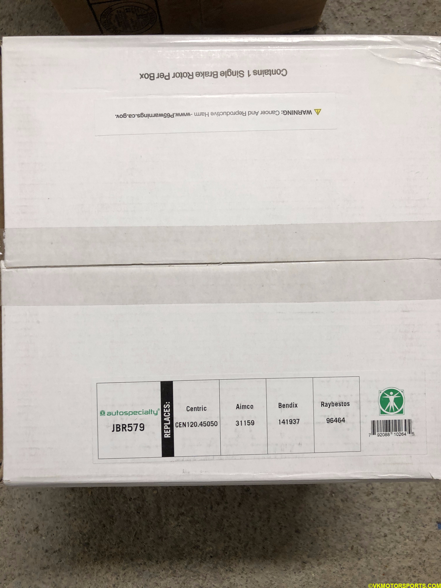 Figure 1a. PowerStop JBR579 front rotor
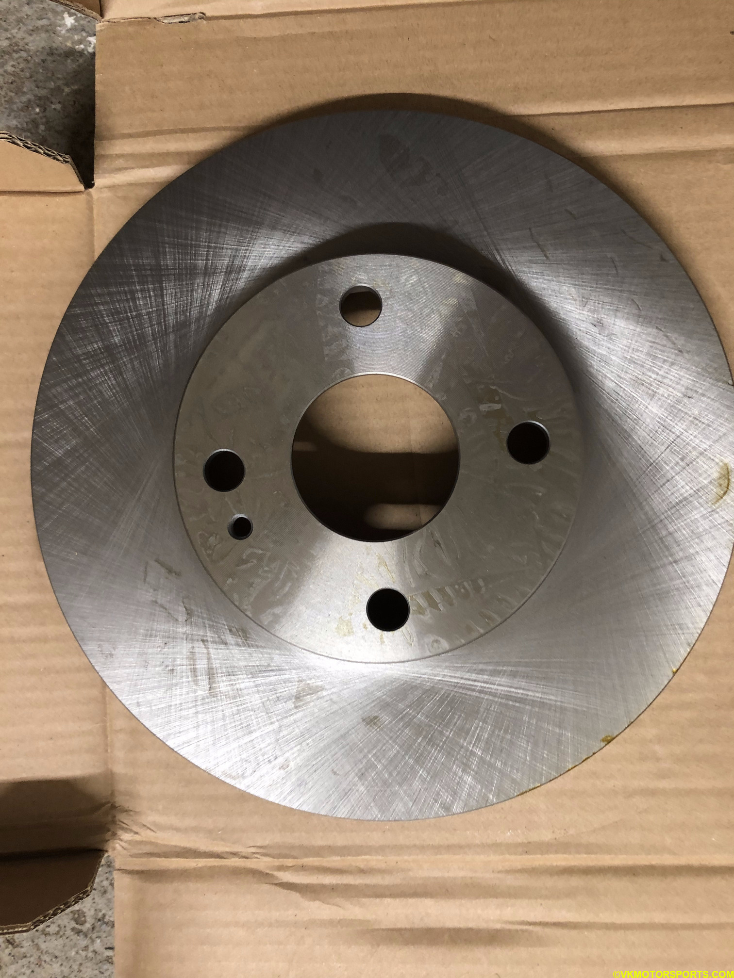 Figure 1b. Front rotor unboxed
- JBR570 for rear rotors by PowerStop
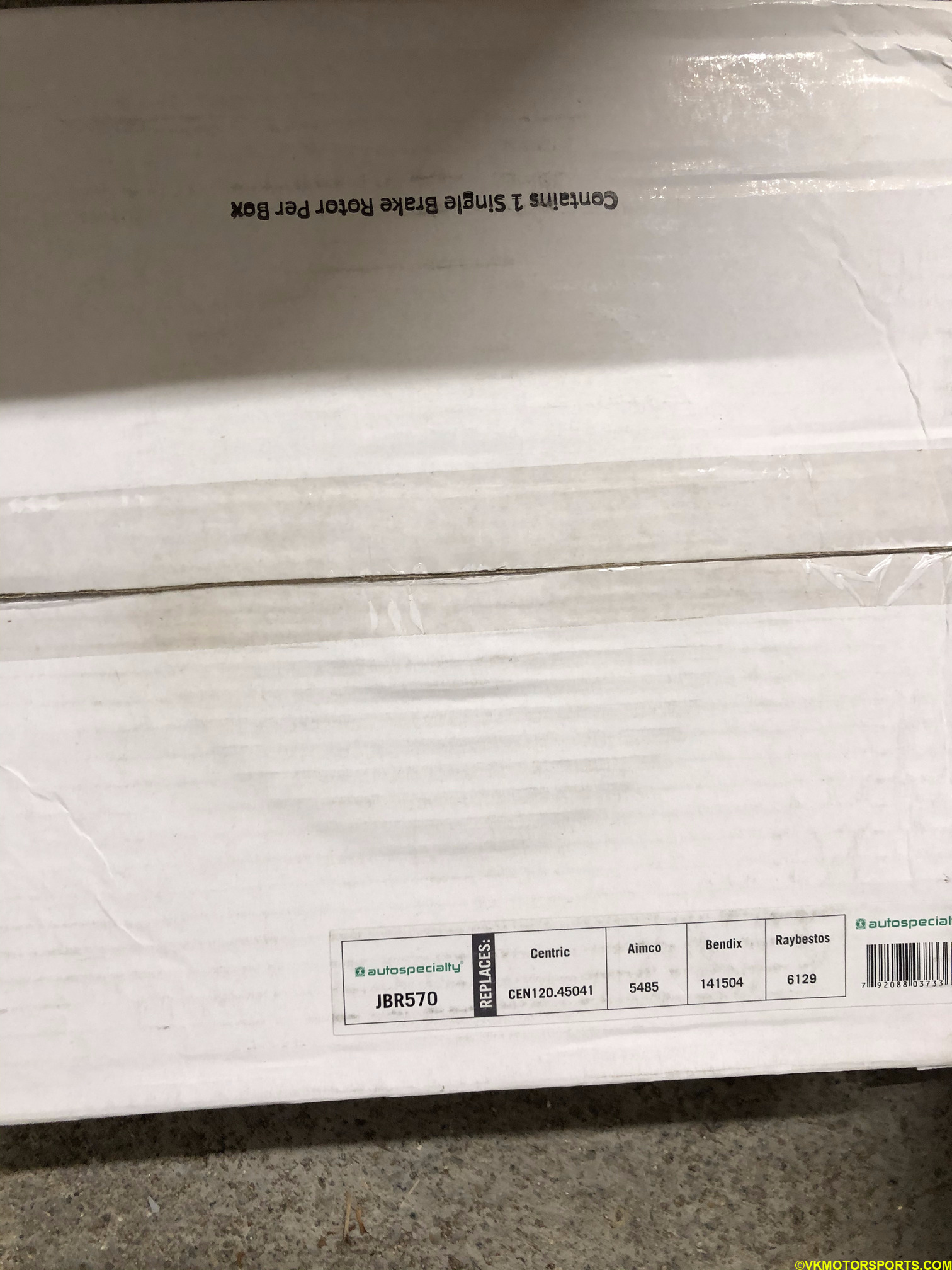 Figure 2. PowerStop JBR570 rear rotors
-
S1377A for rear brake calipers by PowerStop
-
S1704 for front brake calipers by PowerStop
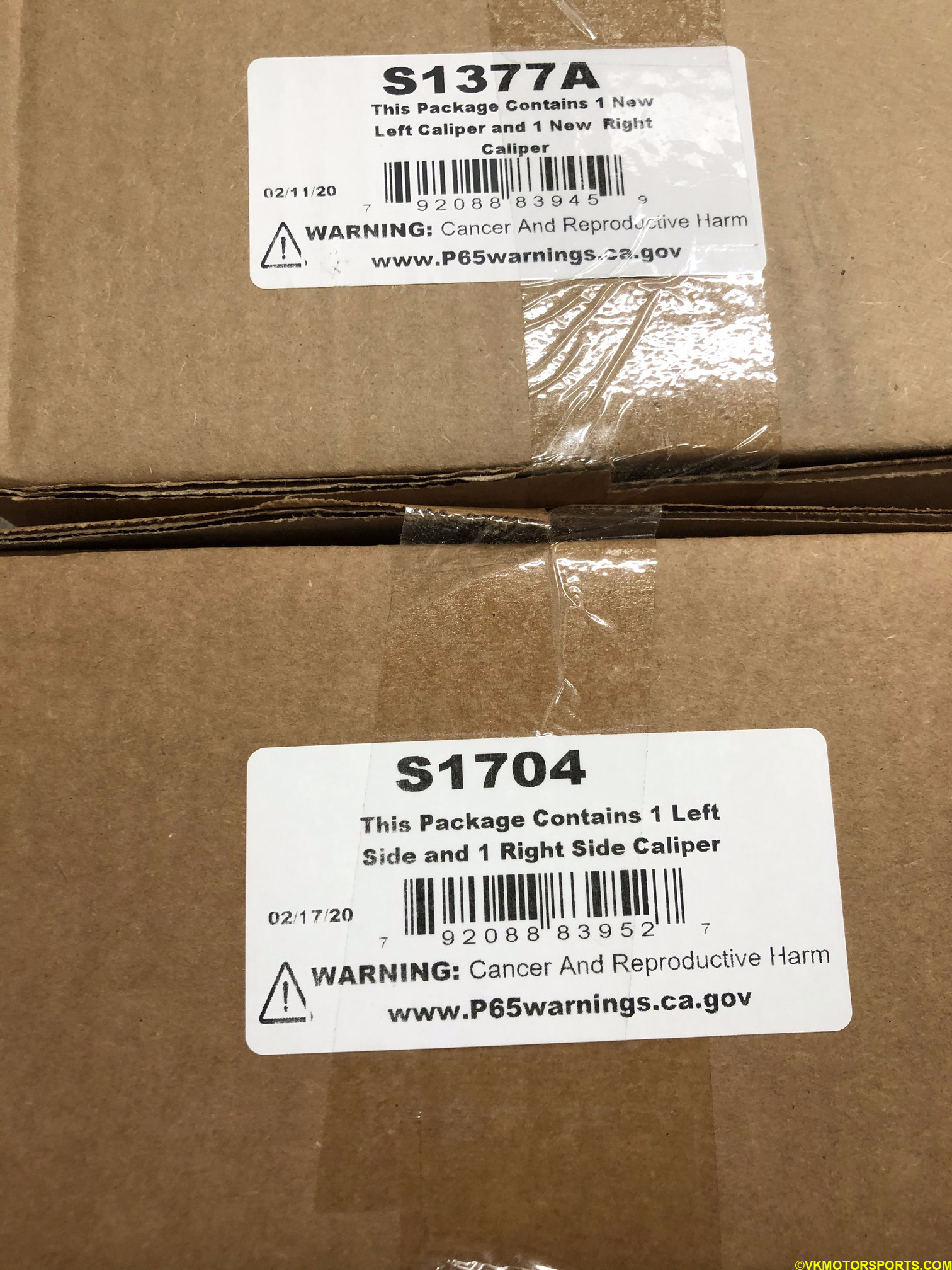 Figure 3. S1377A and S1704 brake calipers by PowerStop
The front rotors must be handled with care using gloves (Figure 4) since they will have sharp edges that can cut deep. The front rotor also is thicker than the rear rotor and has grooves in it as seen in Figure 4.
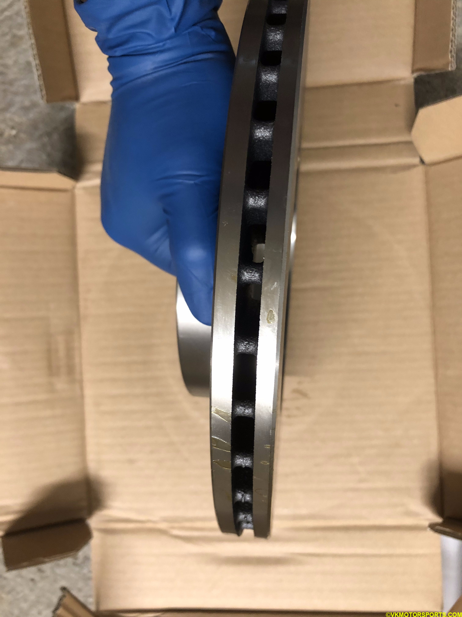 Figure 4. Front rotor side-view. Handle the rotor with gloves
You will also need a 10mm socket and long 14mm socket for removing caliper nuts, a 4mm hex socket, and a 21mm socket for removing the lug nuts on the wheels.
INSTALLING FRONT CALIPERS
Step 1: Using a breaker bar and a 21mm socket (Figure 5a), loosen the lug nuts on all the wheels. Raise the car on jack stands or using a lift. Take off the wheels and keep them aside or under the car for safety.
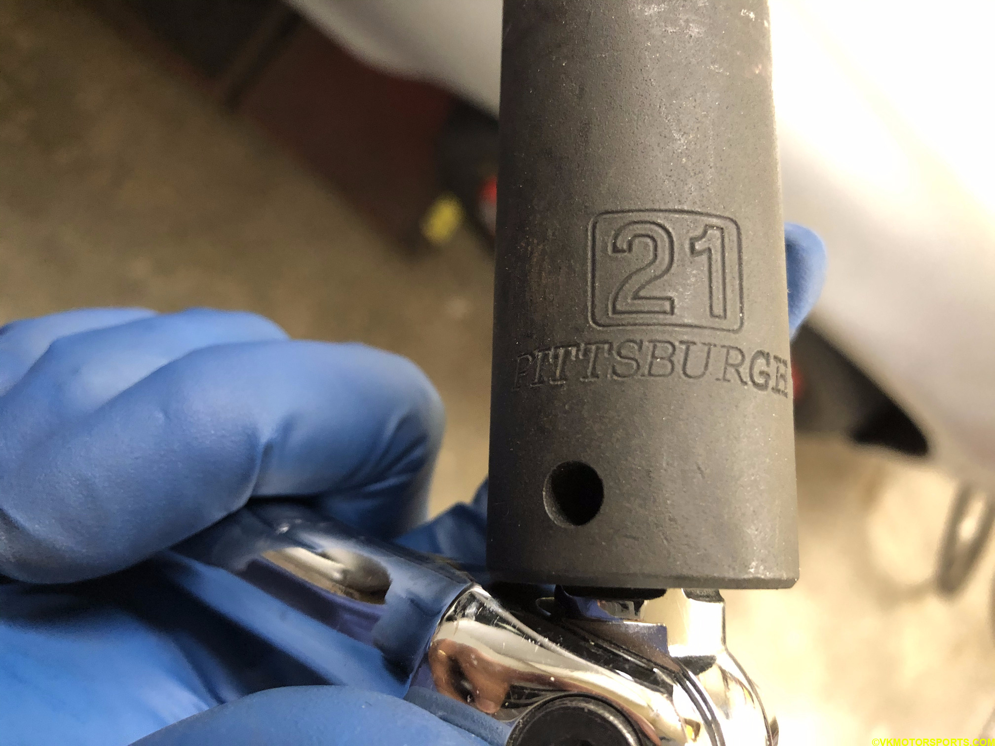 Figure 5. Remove lug nuts using 21mm socket
Step 2: Using a 14mm socket (Figure 6a), loosen the front caliper nut as in Figure 6b and slide it out away from the rotors as shown in Figure 7.
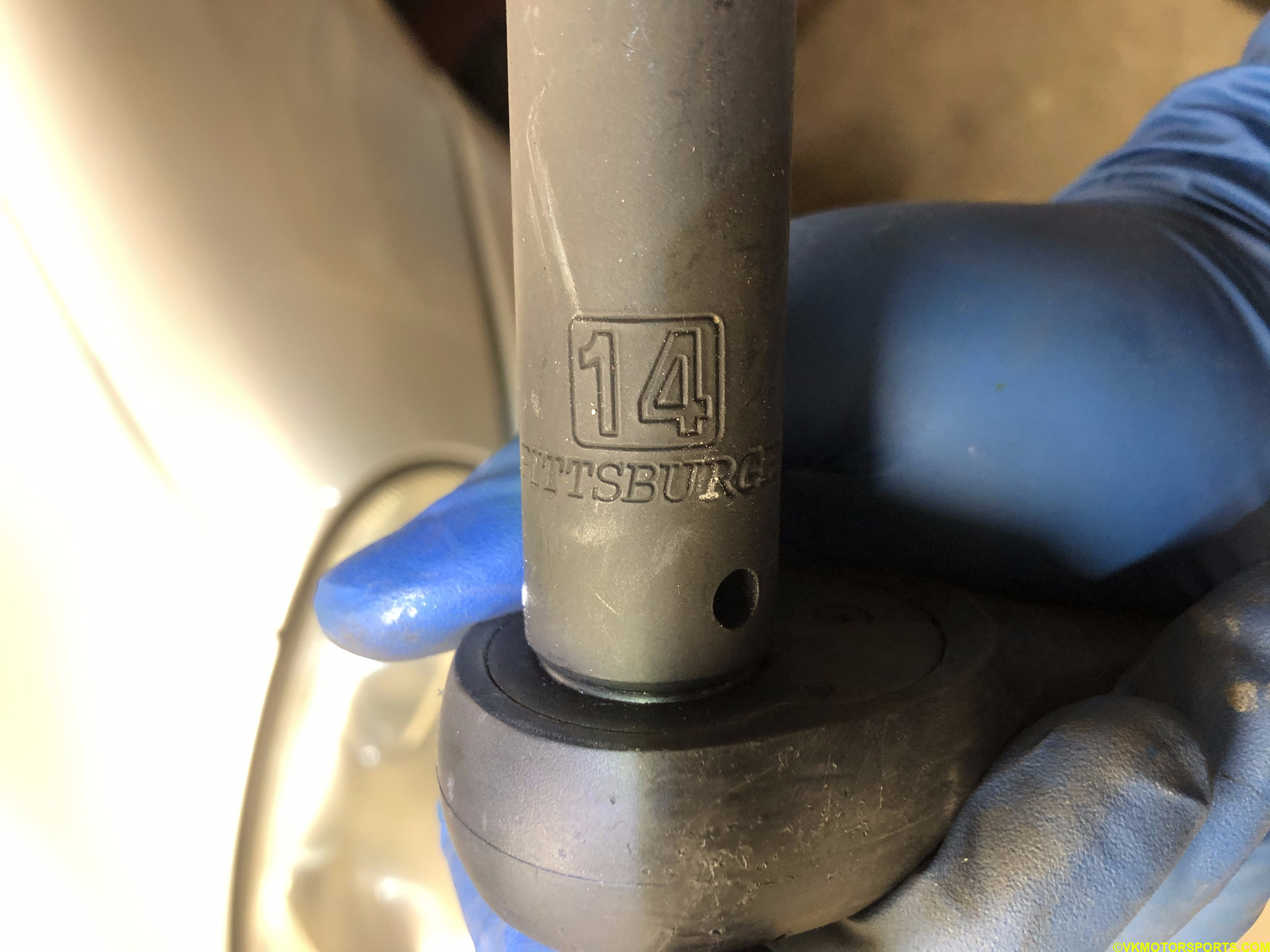 Figure 6a. Use a 14mm socket
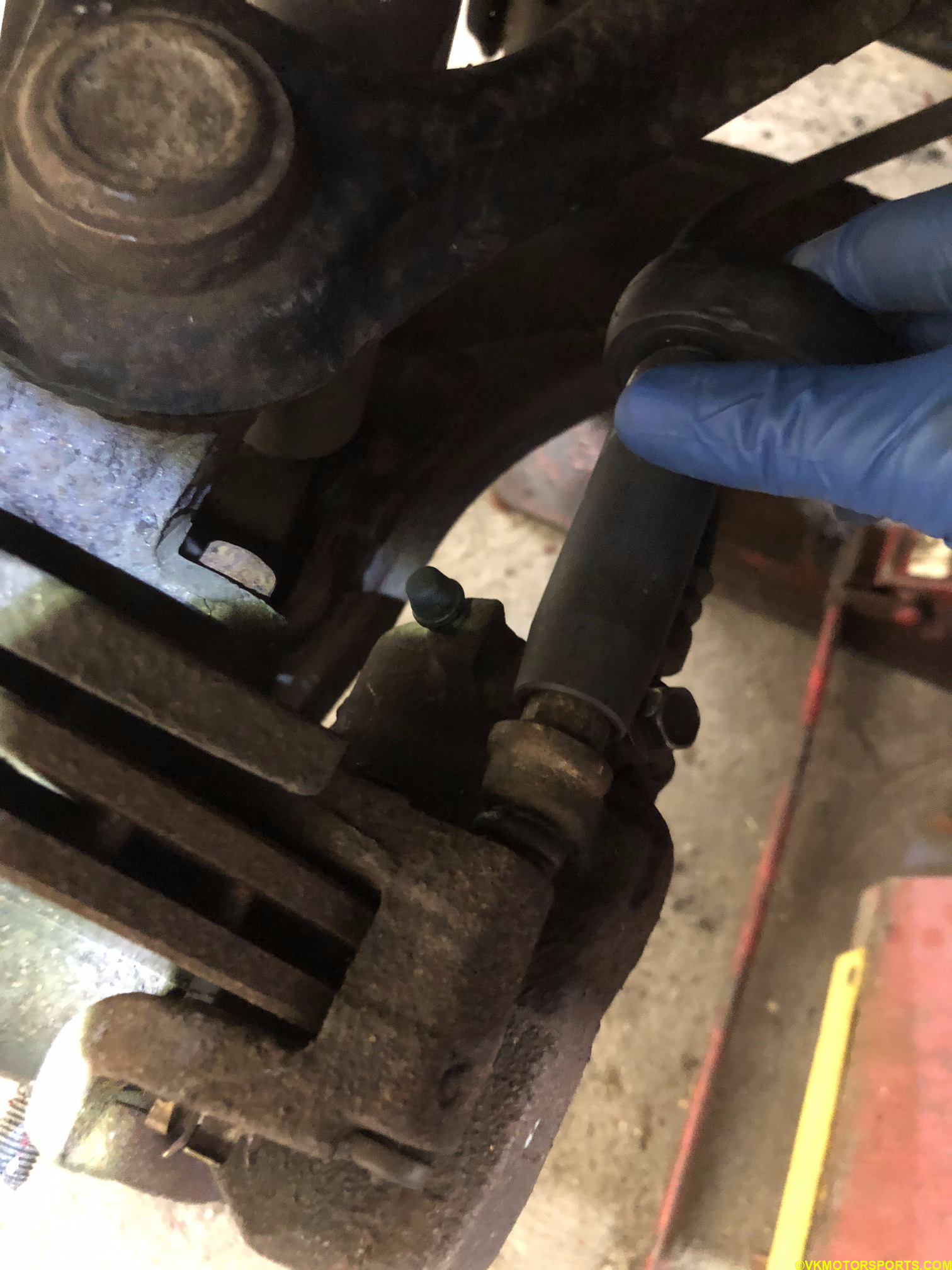 Figure 6b. Loosen the caliper nut with the 14mm socket
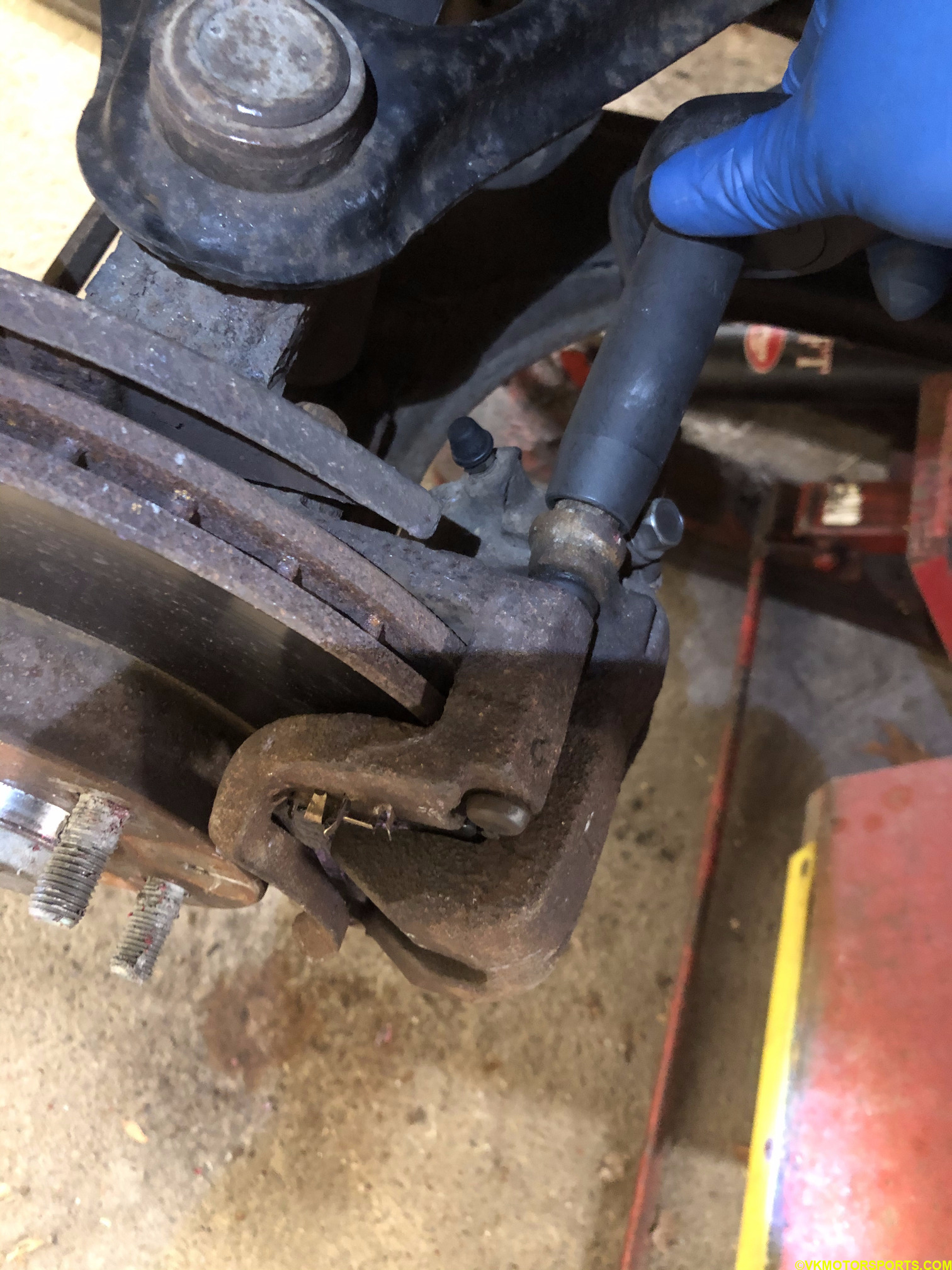 Figure 7. Slide the caliper nut away from the rotor
Step 3: Flip the caliper open and remove the brake pads from the caliper as shown in Figure 8.
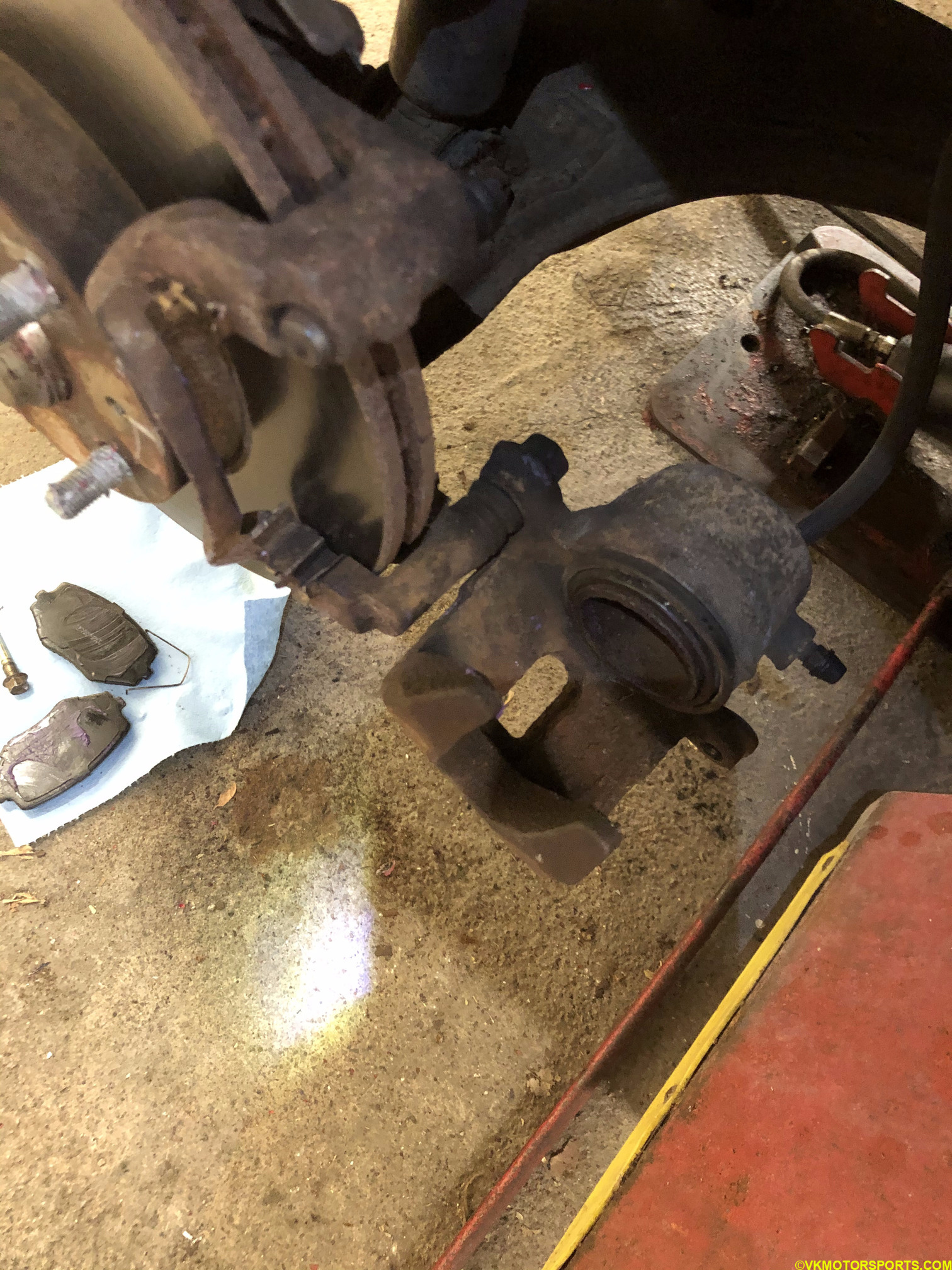 Figure 8. Flip the caliper open and remove brake pads
Step 4: Slide the caliper out slowly from its bottom connector (Figure 9), and place it safely on a control arm or on an upside down bucket so that the brake line is not stressed (Figure 10).
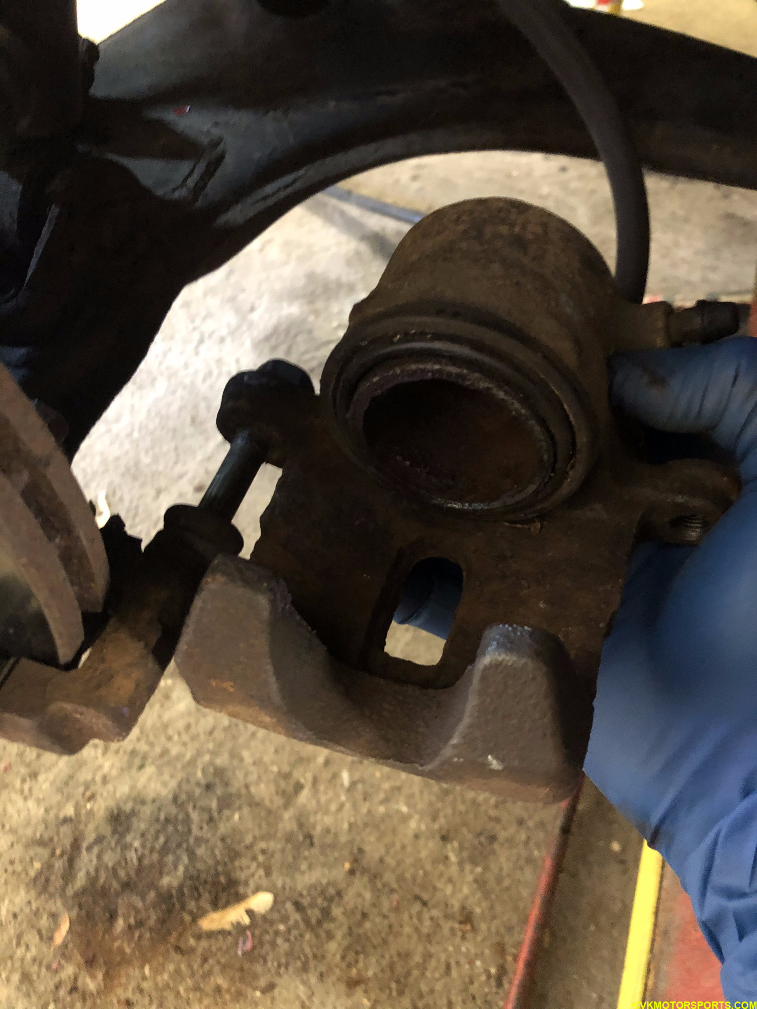 Figure 9. Slide caliper out from the bottom
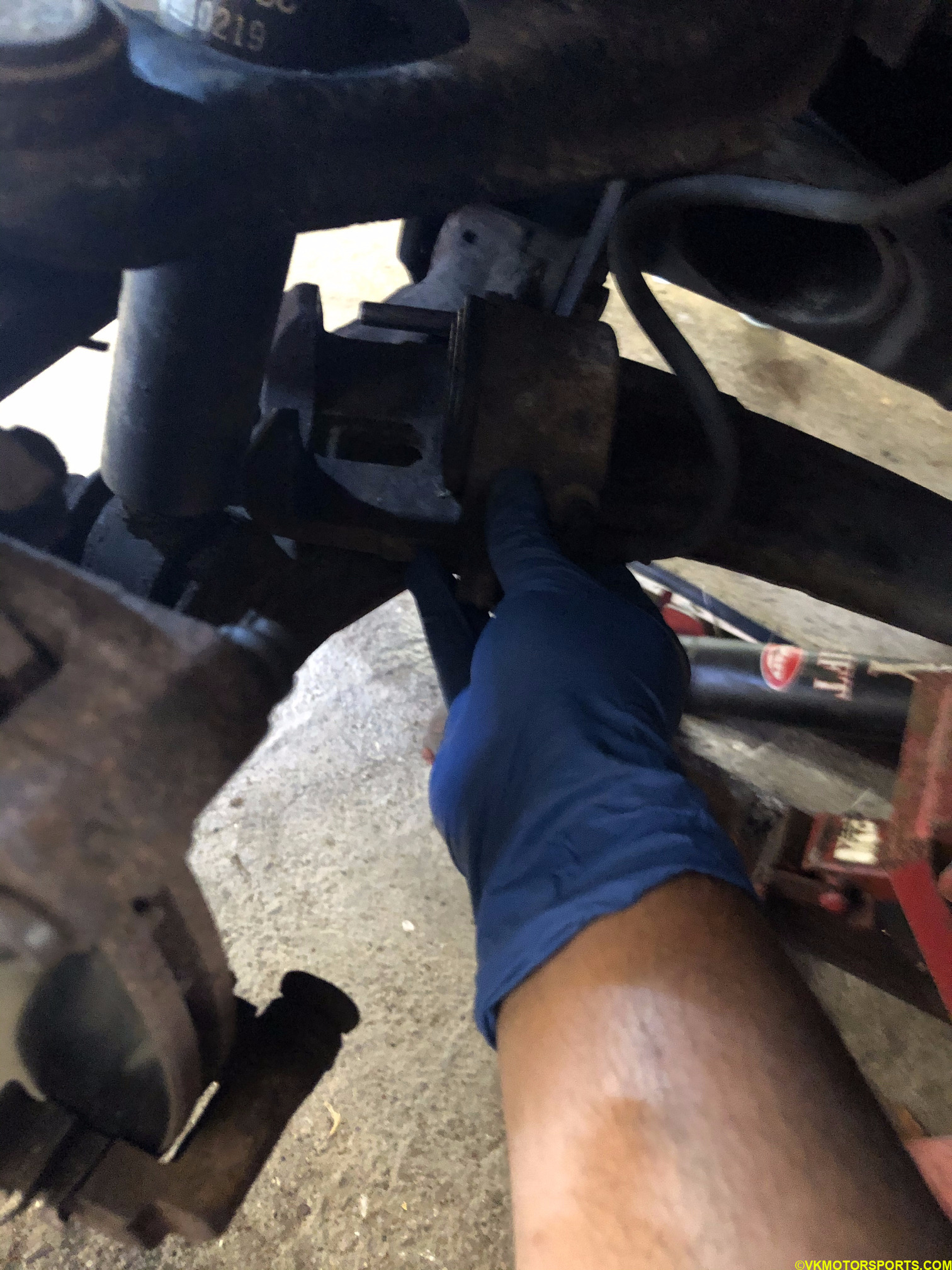 Figure 10. Place caliper safely on a control arm or on a bucket without stressing the brake line
Step 5: Now the rotor is held with a caliper bracket, which has two bolts holding it to the car frame, and needs to be removed. This will enable us to replace not only this bracket but also the rotor. I had to use PB Blaster on the nuts on the bracket.
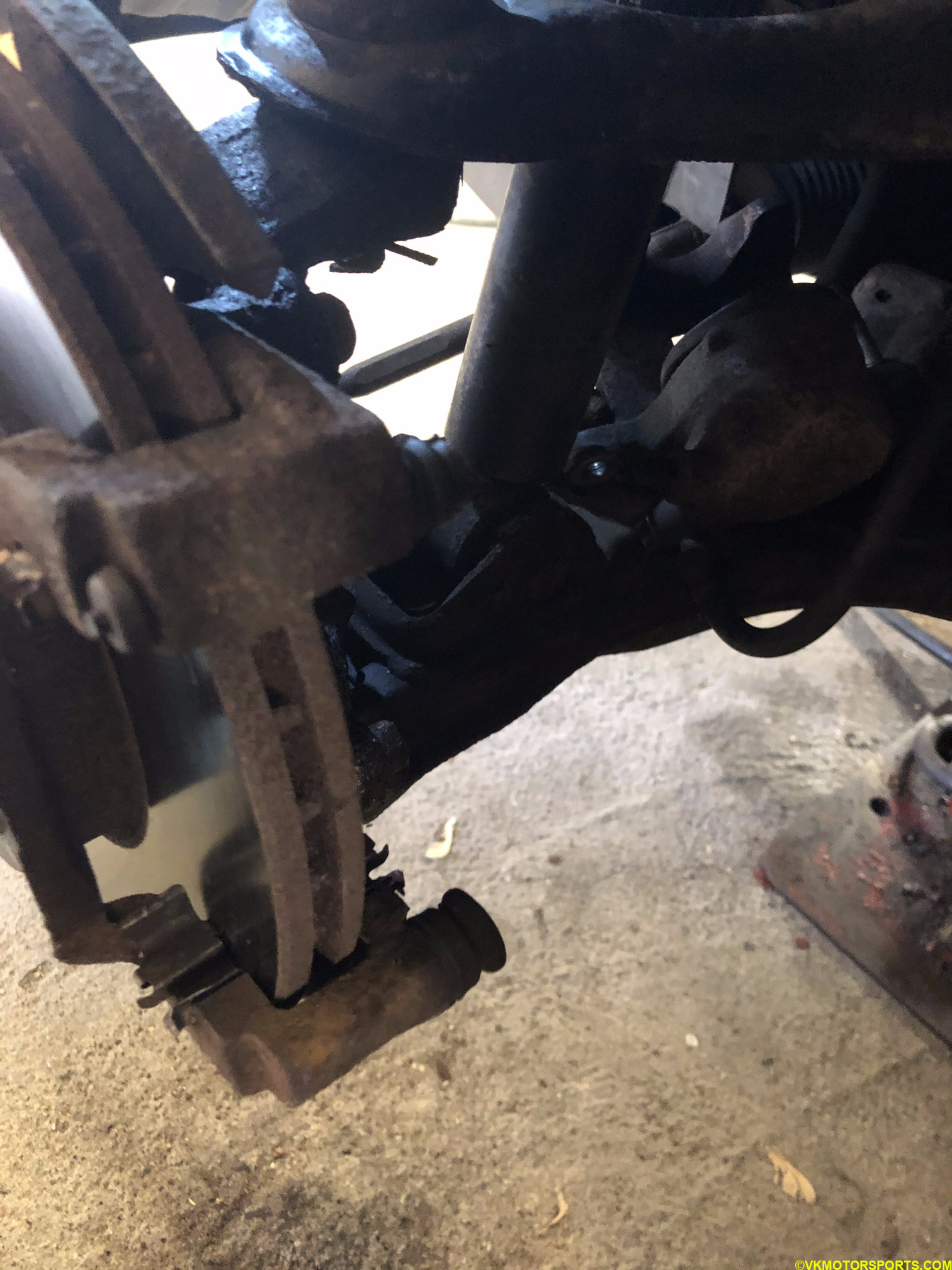 Figure 11a. View of the driver side rotor with the caliper bracket on it
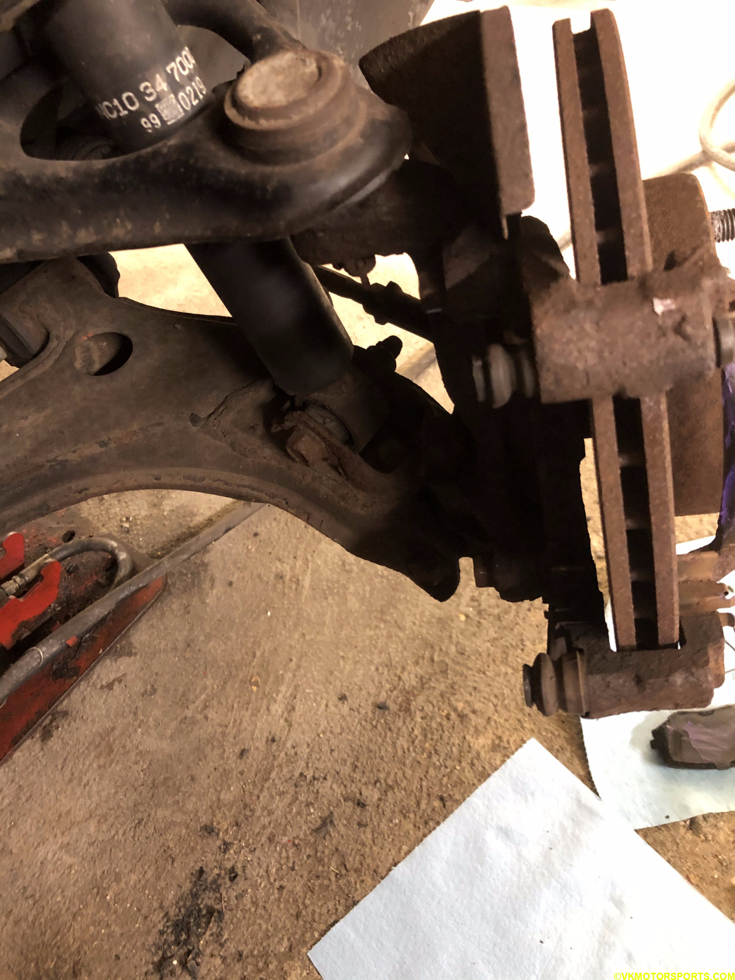 Figure 11b. View on the passenger side of the caliper bracket
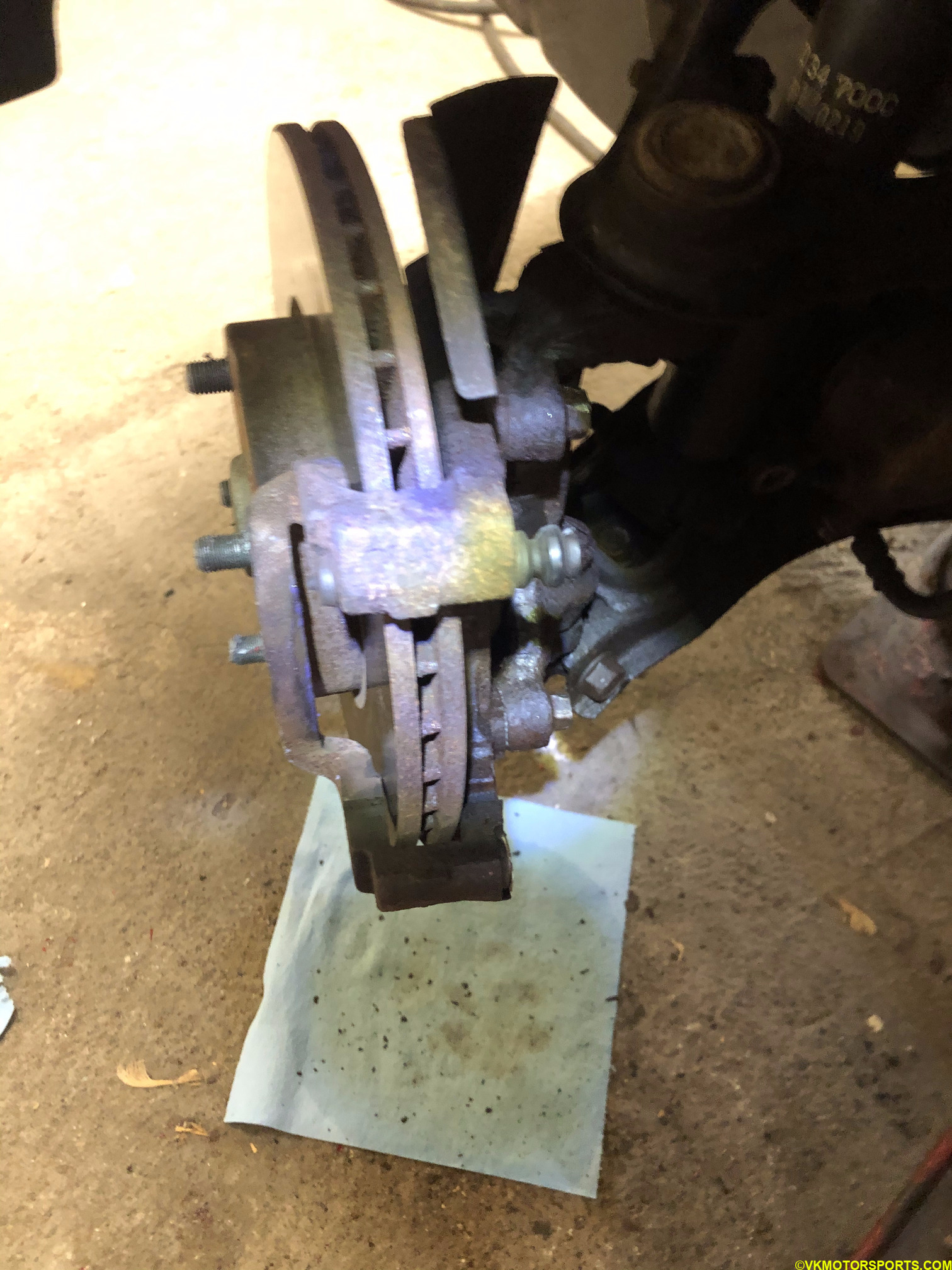 Figure 11c. Different view of the driver side rotor with the caliper bracket
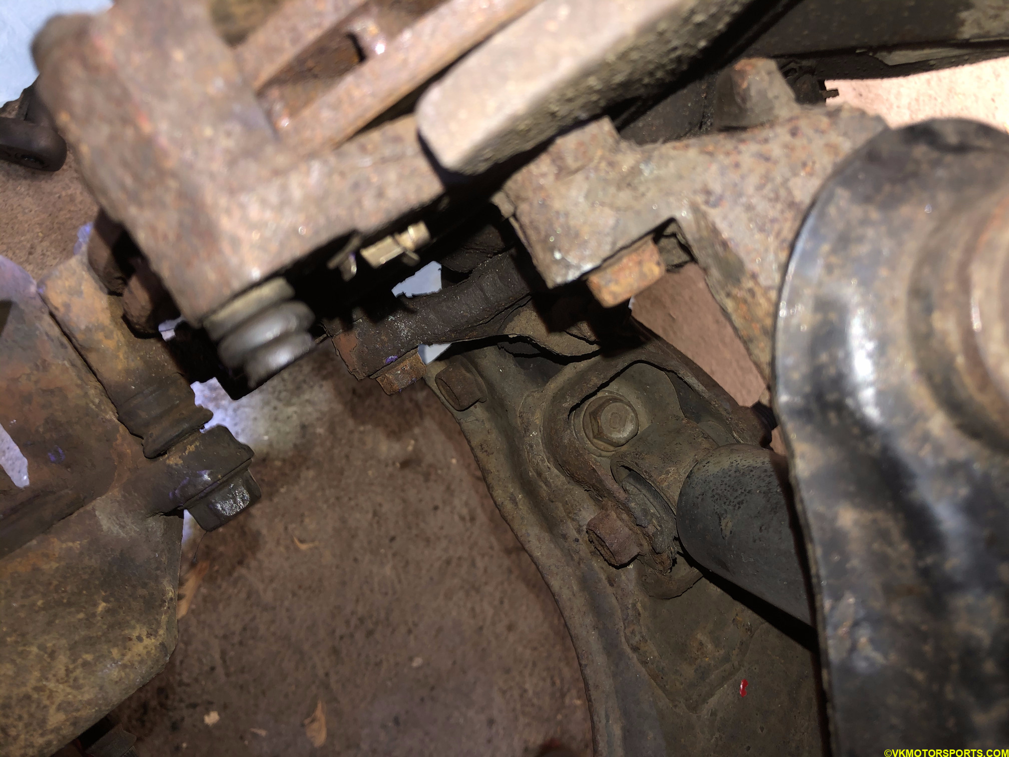 Figure 12. Upper nut view of the brake caliper bracket (left-most in the picture)
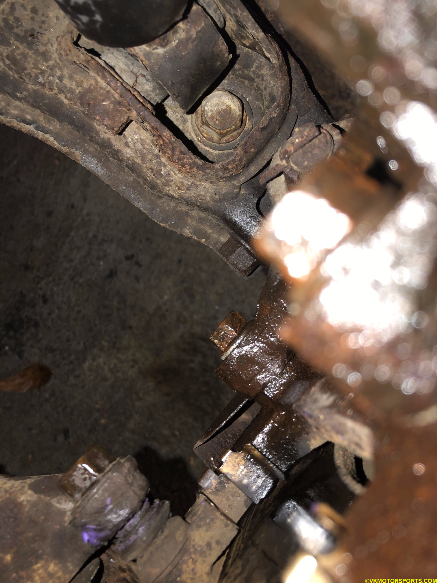 Figure 13. Lower nut view of the brake caliper bracket covered in PB Blaster
Step 6: Remove the caliper bracket and then the rotor, and you should see the wheel hub as seen in Figure 14.
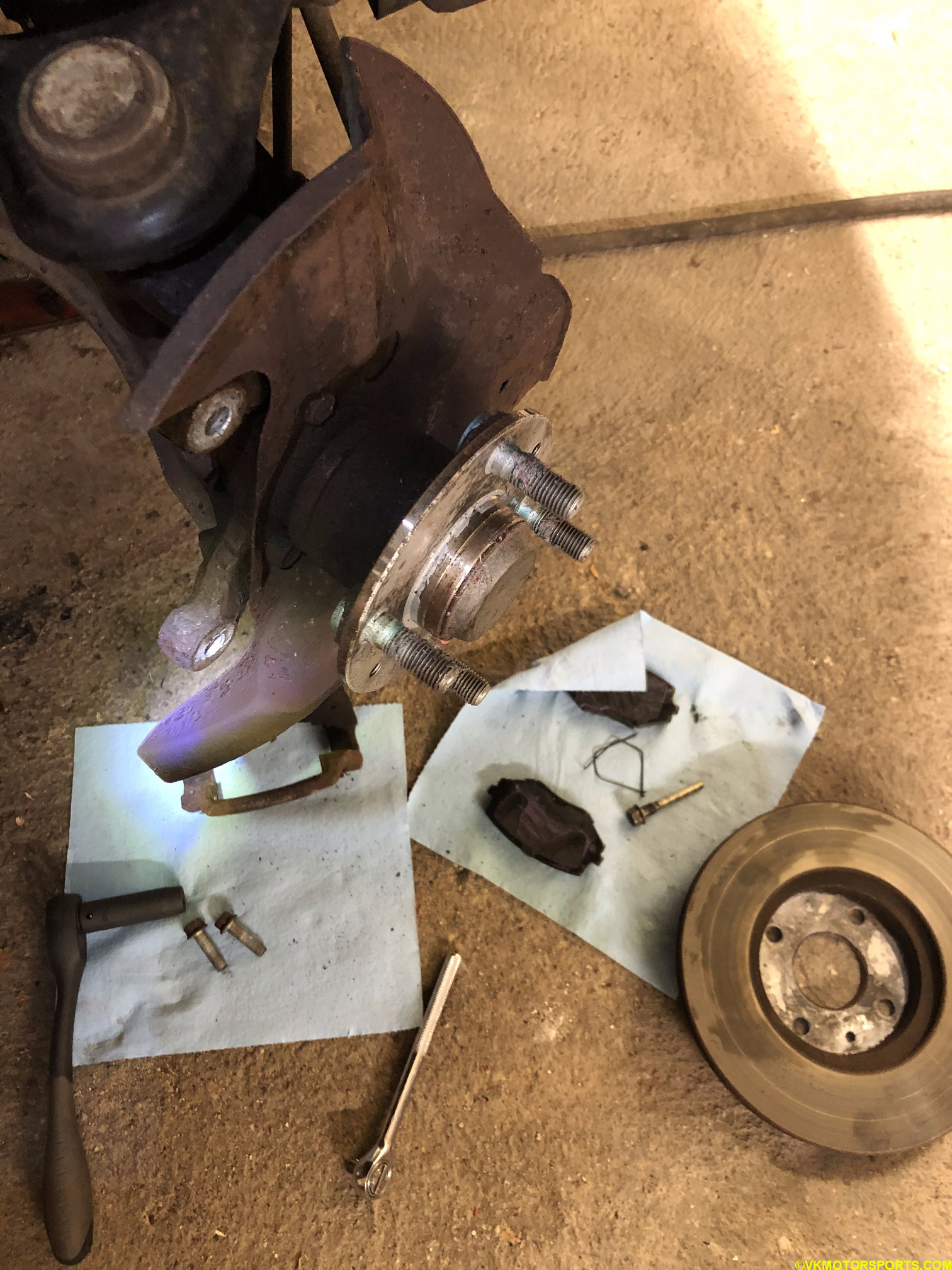 Figure 14. Rotor removed and wheel hub exposed on the passenger side
Step 7: Repeat the same process on the driver side of the the car and remove the rotor.
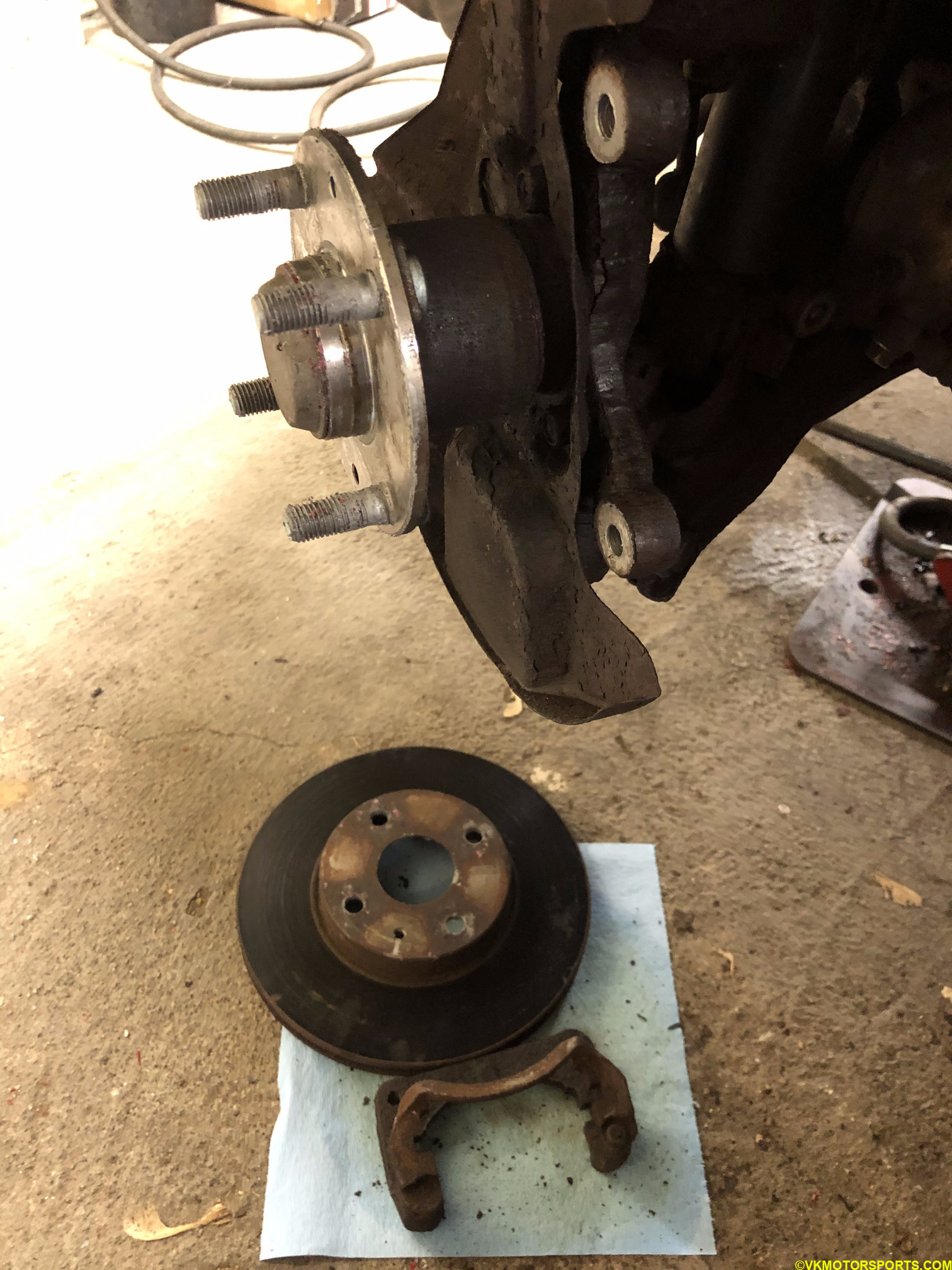 Figure 15. Rotor removed and wheel hub exposed on the driver side
Step 8: This would be a great time to sand the wheel hub and clean it as shown in Figure 16. I would even apply some anti-seize lubricant on the wheel hub.
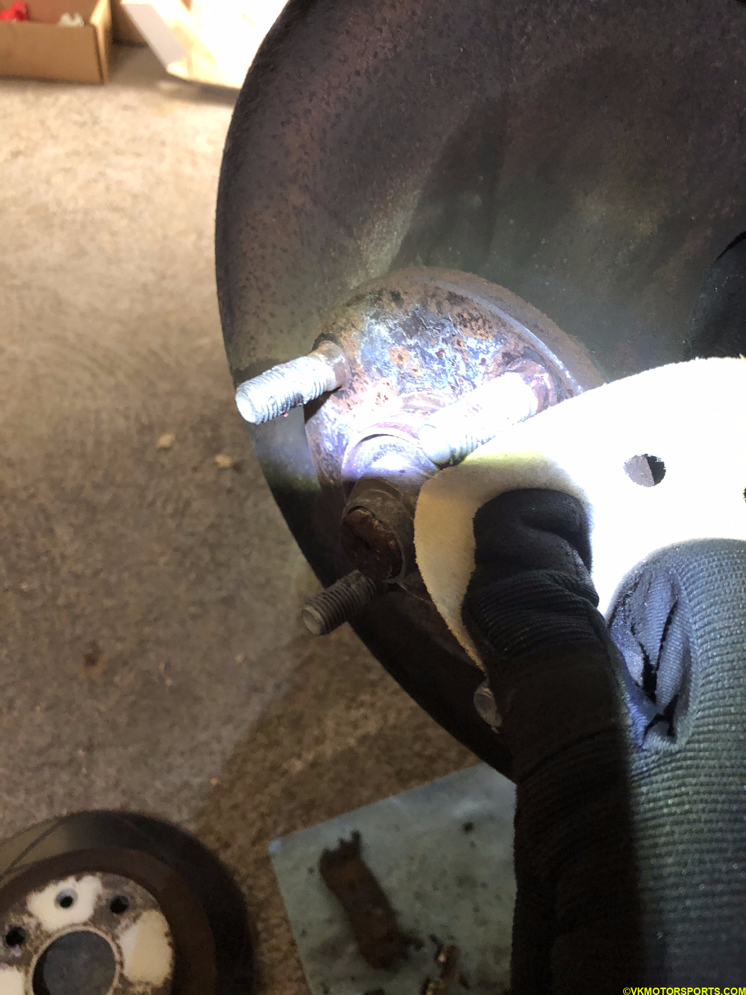 Figure 16. Sand the wheel hub and clean it
Step 9: Unbox the new caliper (Figure 17). You can see that each caliper has the L or R mark depending on which side of the car they are supposed to fit on, as seen in Figure 18.
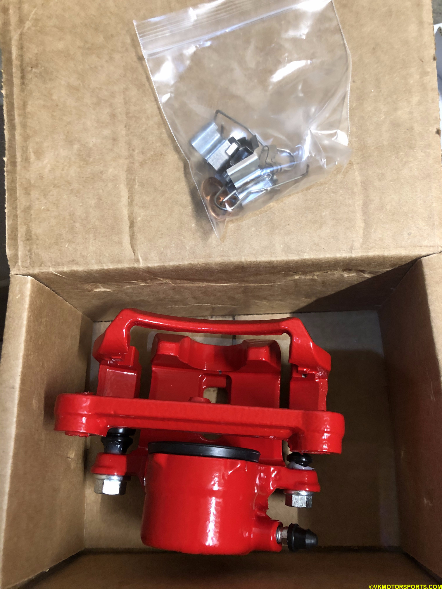 Figure 17. Unbox the new caliper
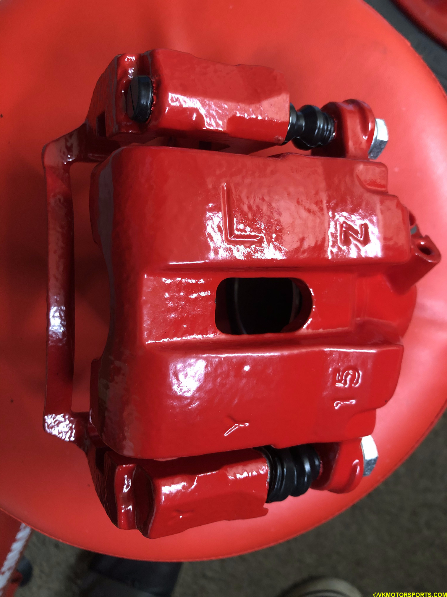 Figure 18. L marked on the front caliper for the driver side
Step 10: Take a new rotor from the box (Figure 29) and install it on the wheel hub. Add 2 lug nuts to hold it in place as shown in Figure 30. This is needed so that you can install the caliper without the rotor moving out of place.
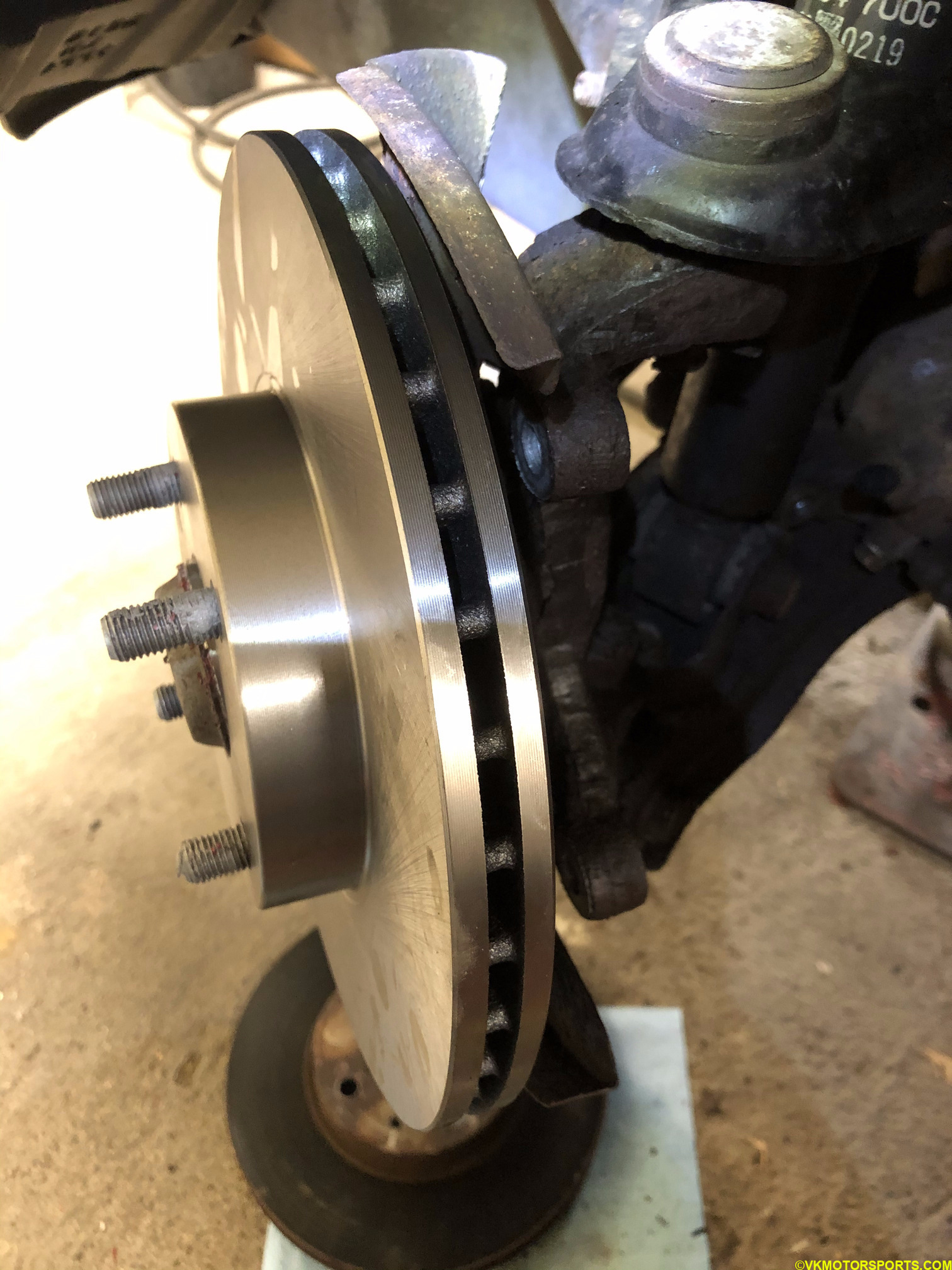 Figure 19. Install the new rotor on the wheel hub
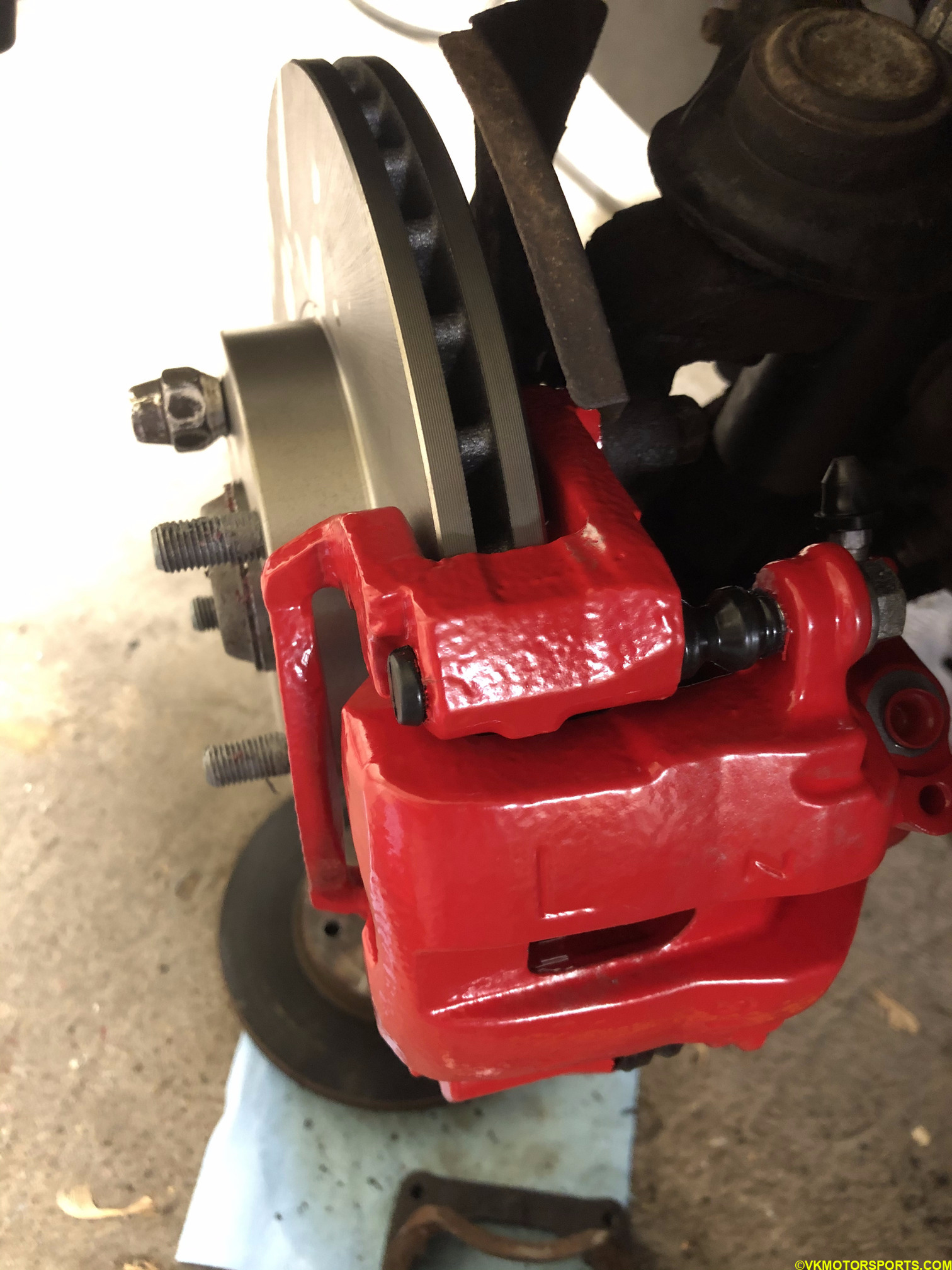 Figure 20. Place new rotor on the wheel hub and hold it in place with 2 lug nuts
Step 11: Installation of the new caliper is exactly the same as the removal but in reverse.
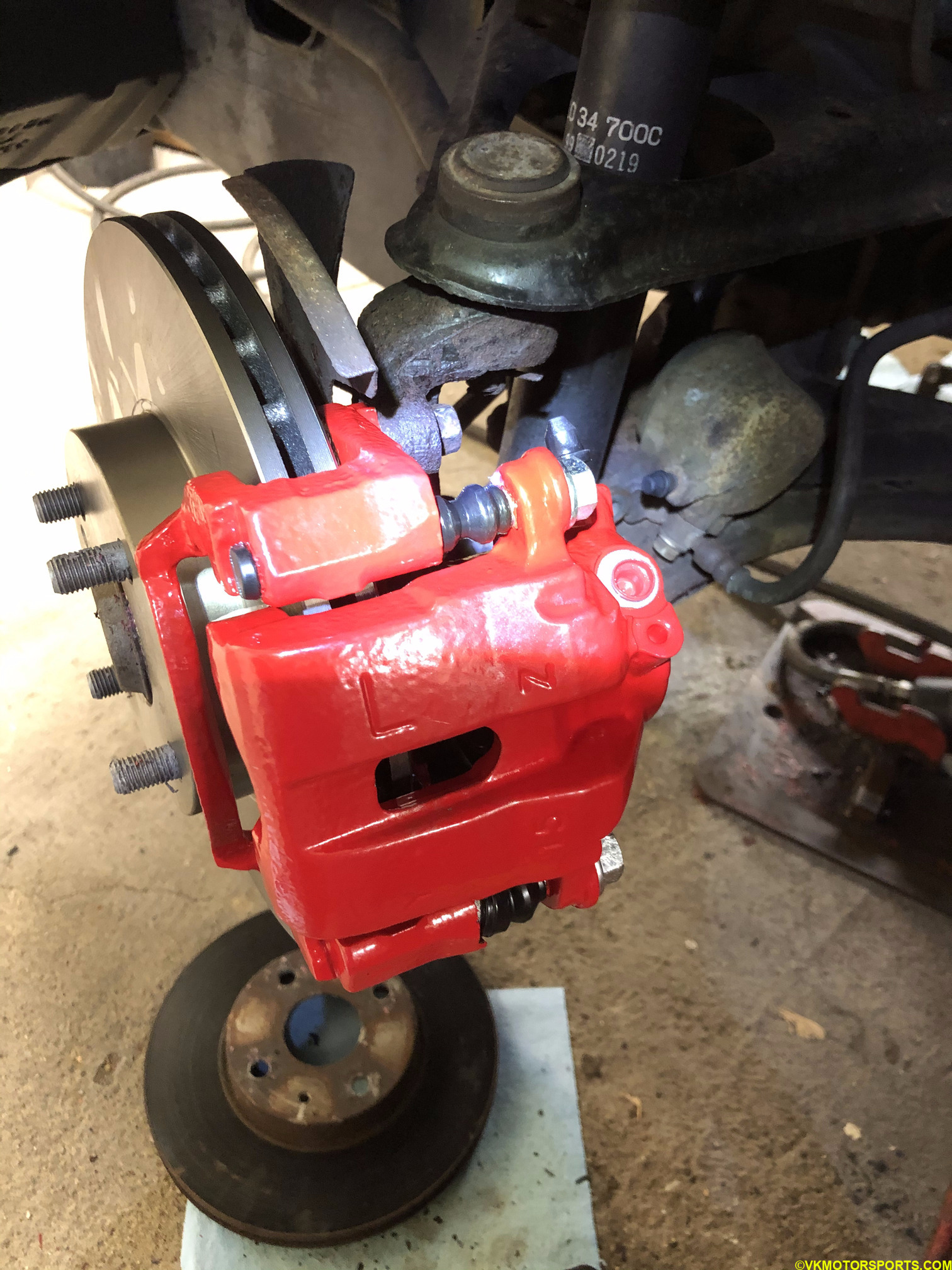 Figure 21. L marked caliper installed on the driver side front wheel hub
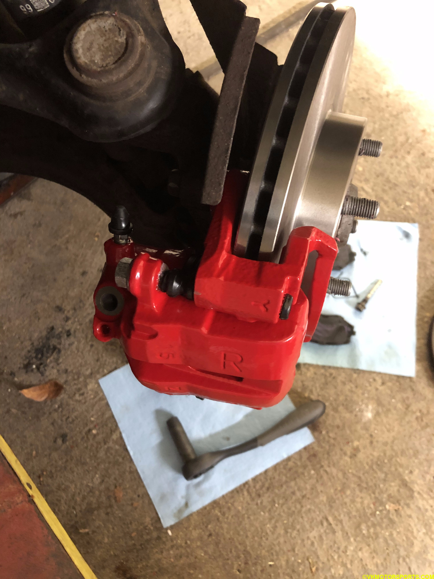 Figure 22. R marked caliper installed on the passenger side front wheel hub
You may have noticed in Figure 22 that I have not installed the brake pads yet.
INSTALLING REAR CALIPERS
Step 1: Using a breaker bar and a 21mm socket (Figure 5), loosen the lug nuts on all the wheels. Raise the car on jack stands or using a lift and pull the parking brake (e-brake) as in Figure 23. Take off the wheels and keep them aside or under the car for safety.
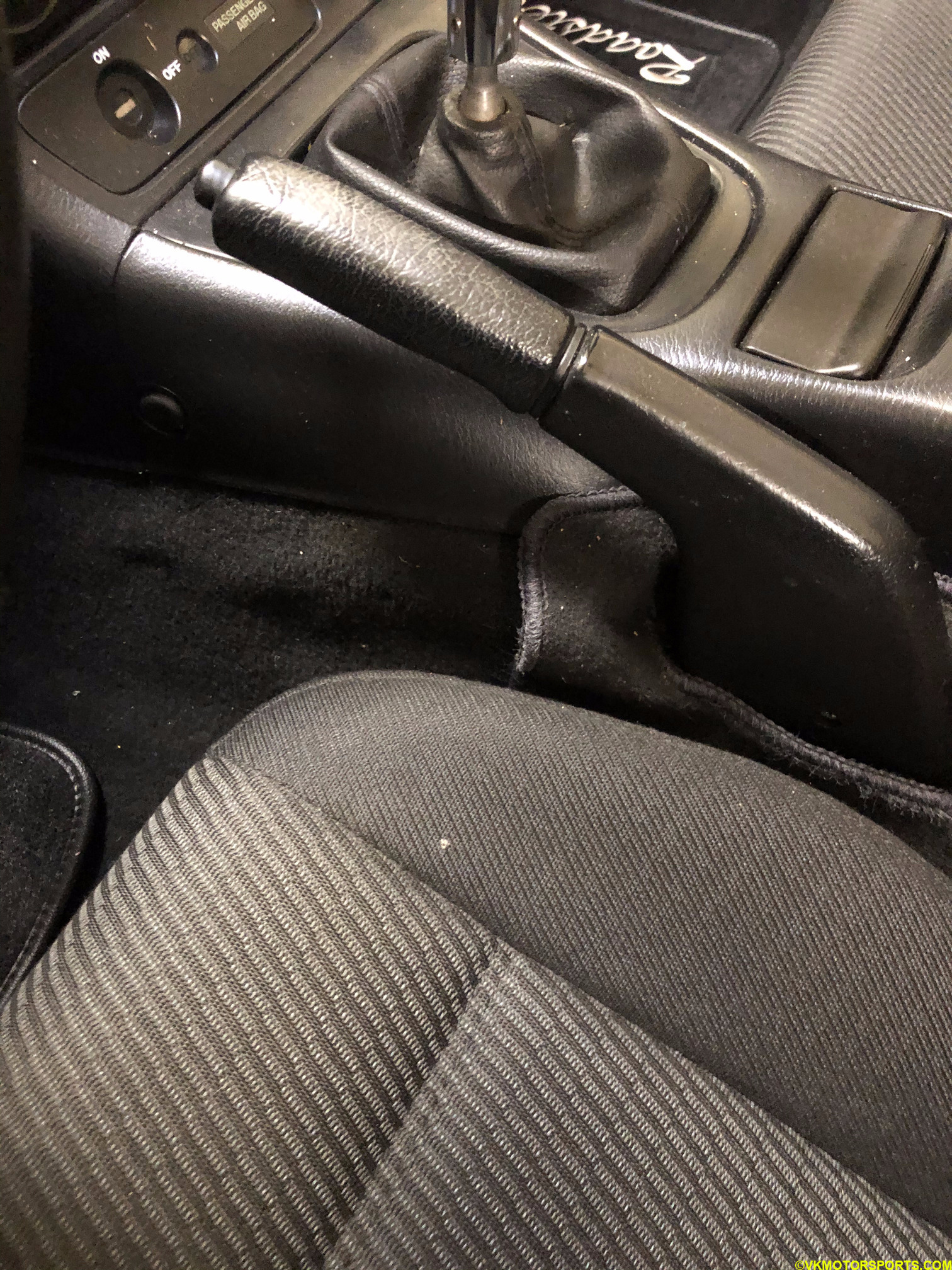 Figure 23. Pull the e-brake
Step 2: Take a look at the rusty old rear caliper in Figure 24 and the unboxed remanufactured replacement purchased from RockAuto in Figure 25a and 25b. These are the same, stock Mazda calipers, since the Miata is an autocross car in the E-class and needs to stay stock.
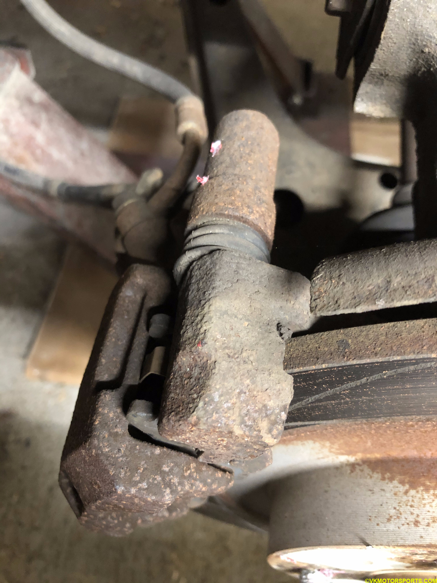 Figure 24. Rear caliper view
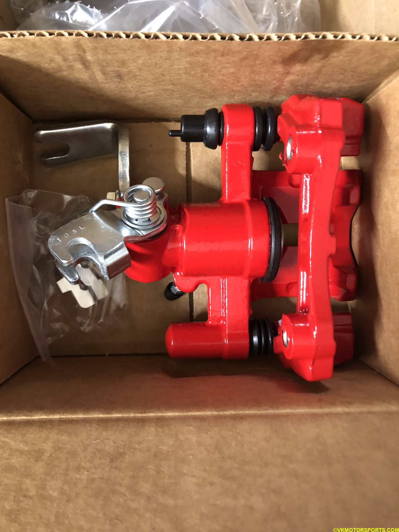 Figure 25a. Unboxed replacement rear caliper
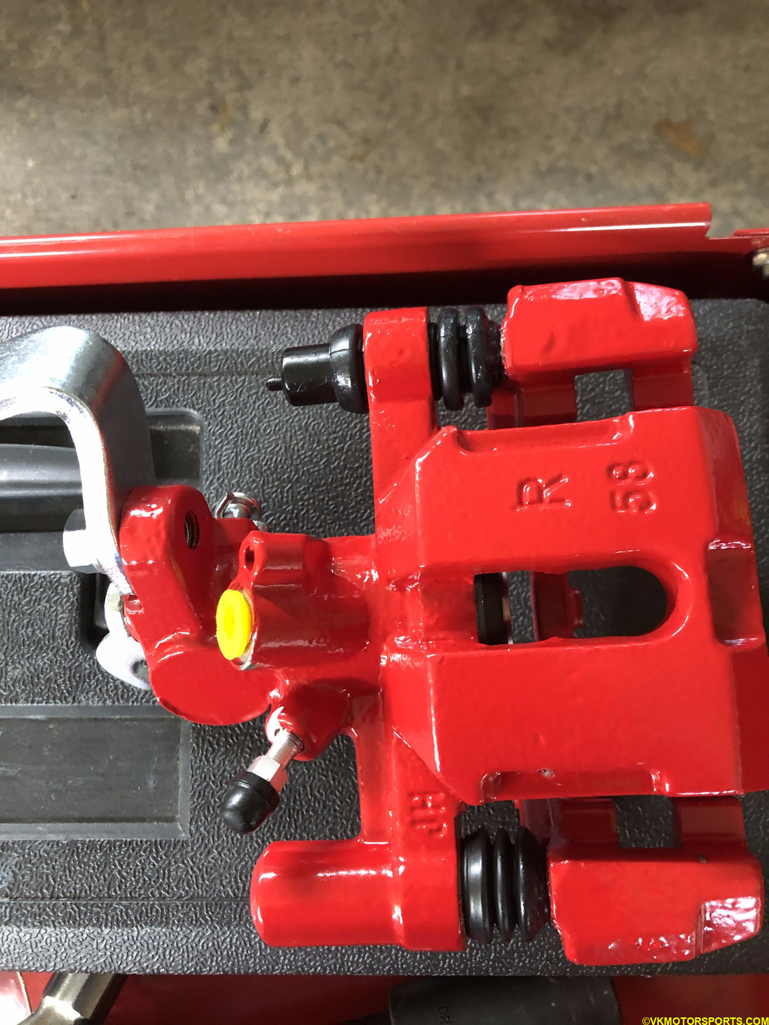 Figure 25b. Passenger side rear caliper
Step 3: Place a container below the brake line in case brake fluid overflows. You will be loosening the nuts visible in Figures 26 and 27 using a 14mm socket or wrench. This is the rear driver side of the car being shown in these pictures.
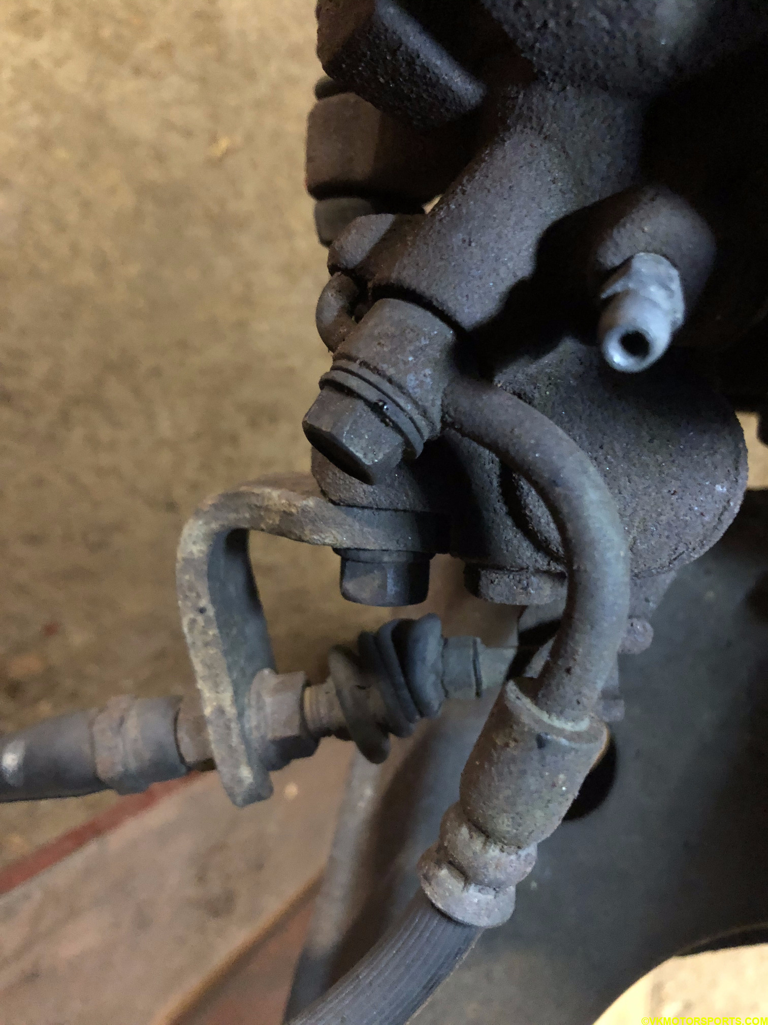 Figure 26. Rear caliper brake line
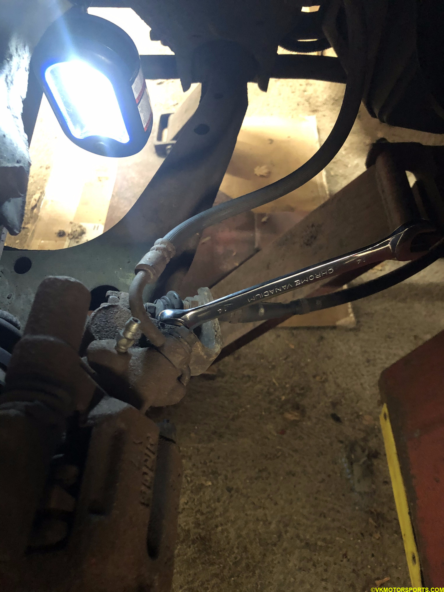 Figure 27. Loosen the nuts using a 14mm socket or wrench
Step 4: Remove the e-brake cover nut to expose the hex nut. Loosen the hex nut using 4mm hex socket as shown in Figure 32.
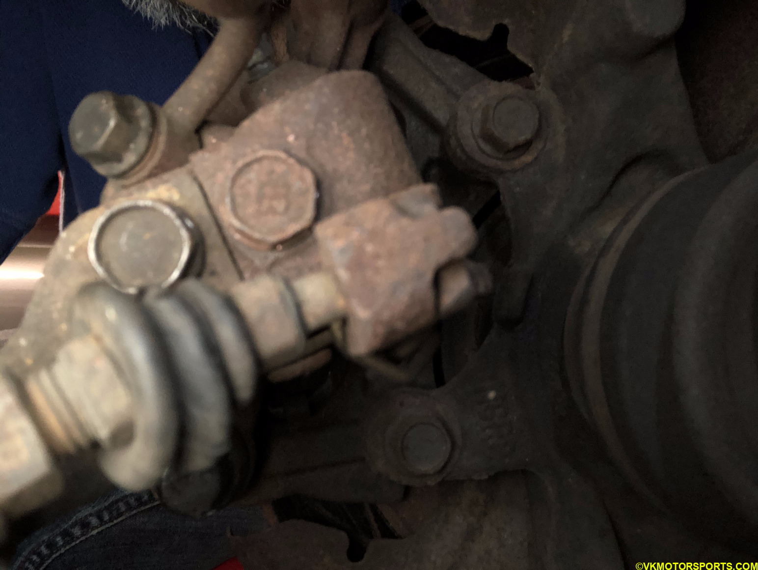 Figure 28. View of the e-brake nut from behind the wheel
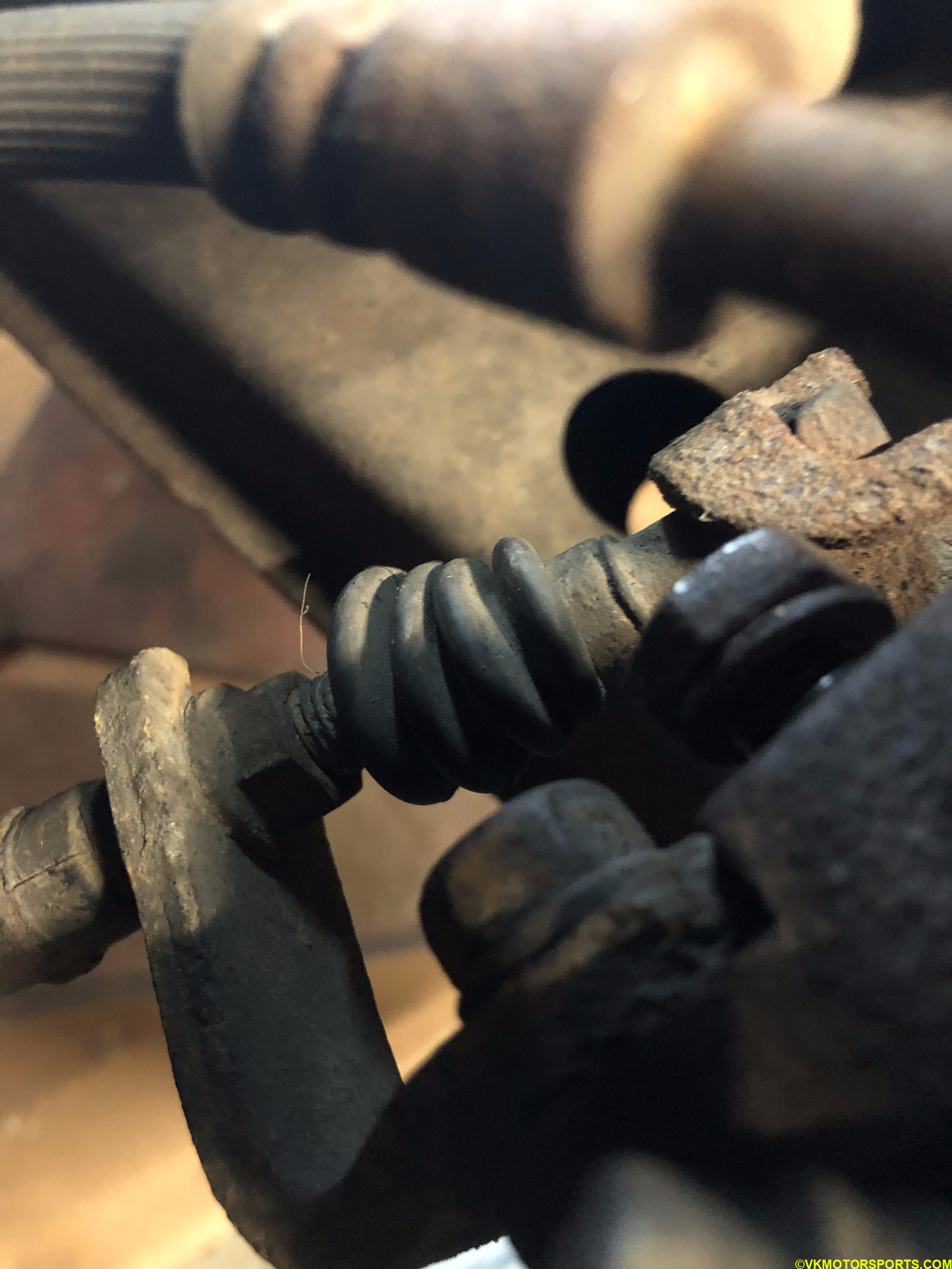 Figure 29. View of the e-brake nut from front of the wheel
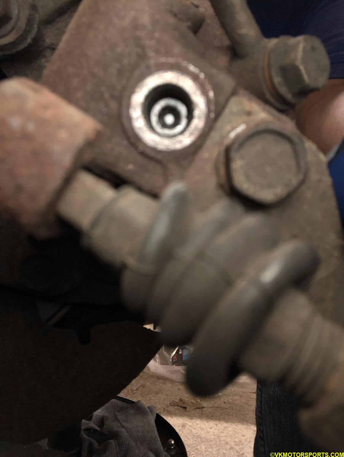 Figure 30. View of the e-brake nut removed exposing the hex nut in there
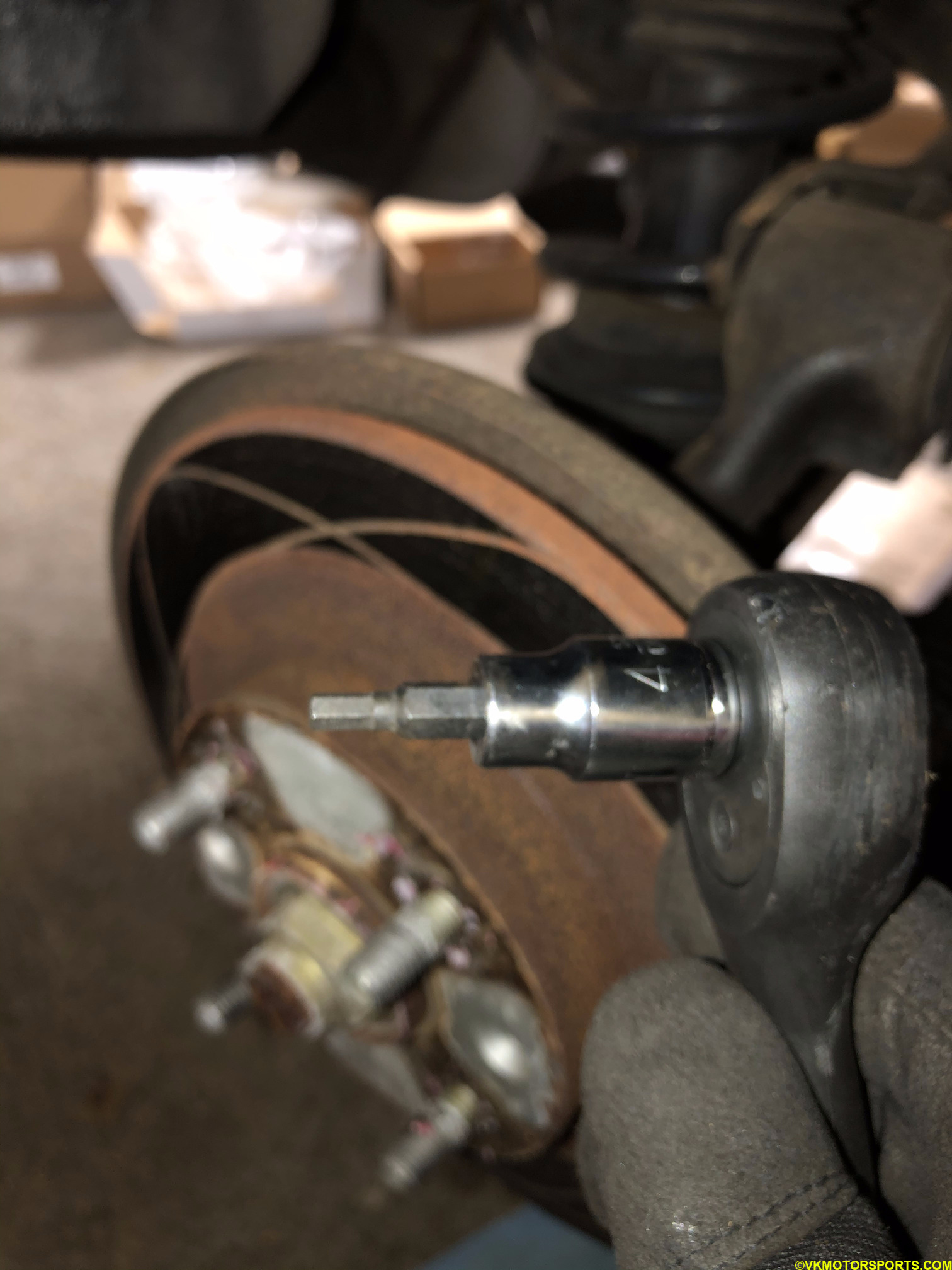 Figure 31. 4mm hex socket
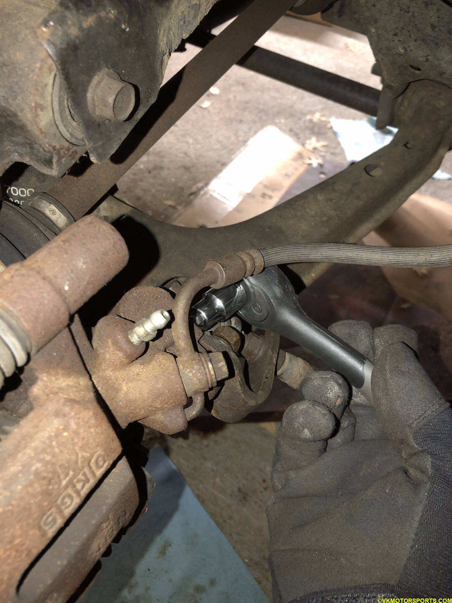 Figure 32. Loosen the hex nut
Step 5: Take off the rubber cap on the side of the caliper that’s facing inward from the front of the wheel as seen in Figure 33. There is a 10mm nut hiding behind it. Using a 10mm socket remove that nut as shown in Figure 34 and 35. Once the nut has been loosened you will notice it is a slide pin, as in Figure 36.
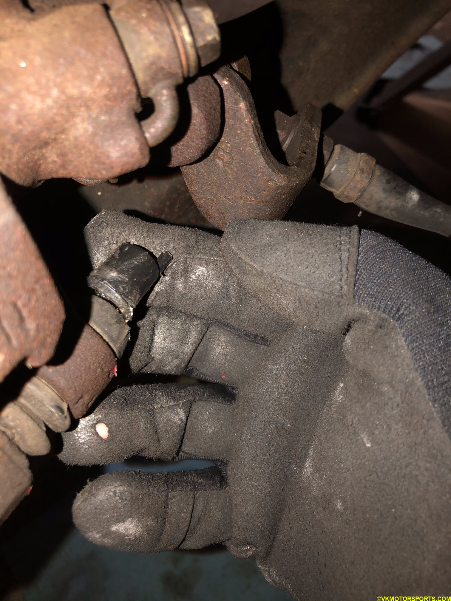 Figure 33. Remove the rubber cap on the rear facing side of the caliper
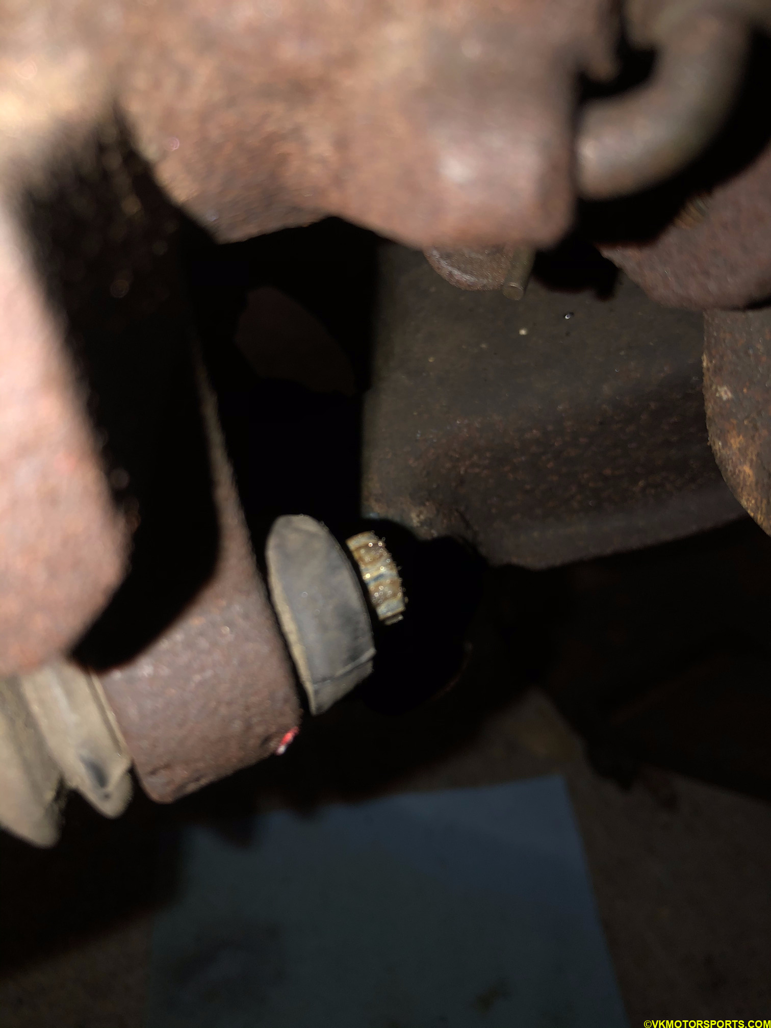 Figure 34. Look at the nut hiding behind the rubber cap
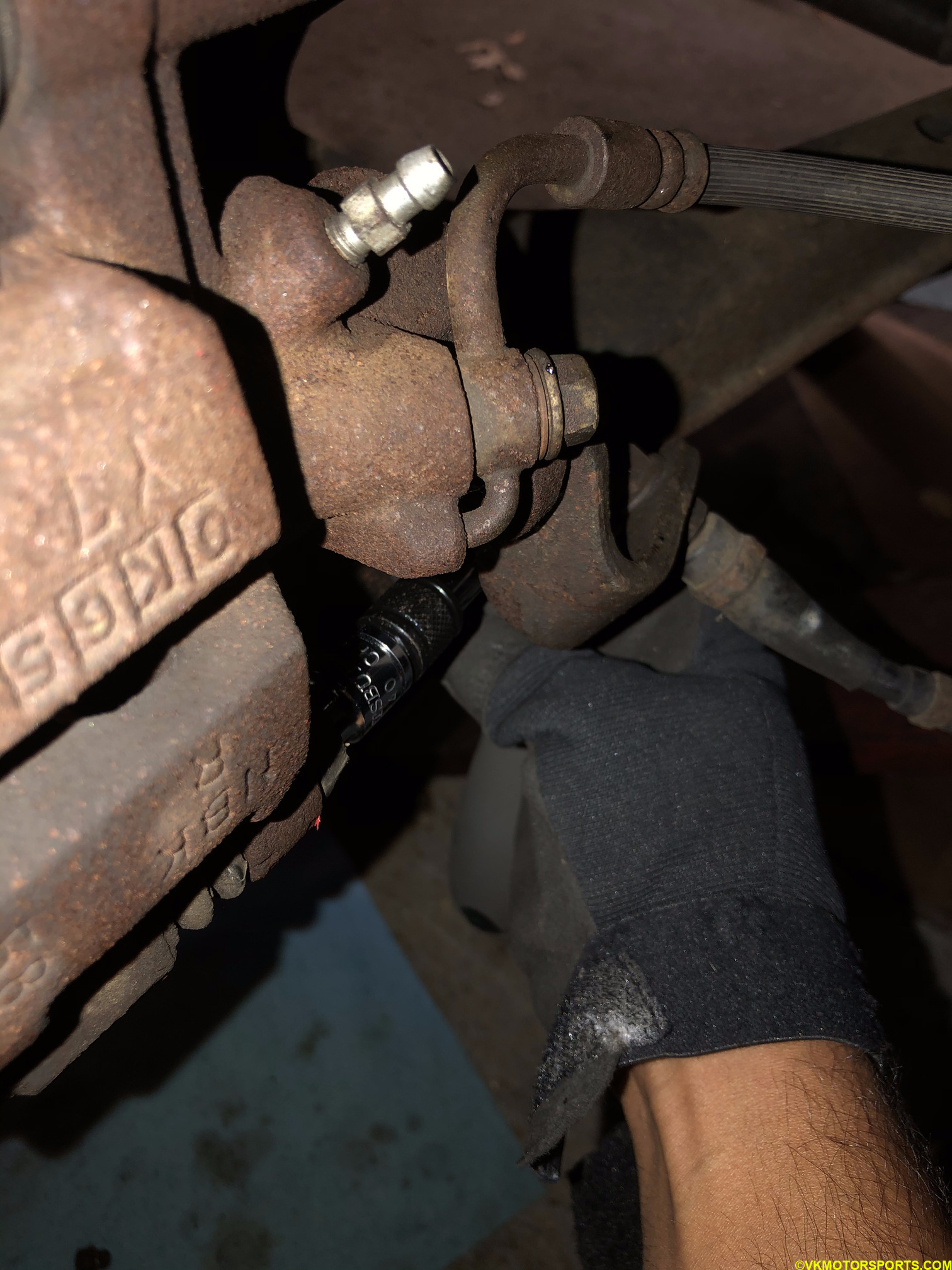 Figure 35. Loosen the nut using a 10mm socket
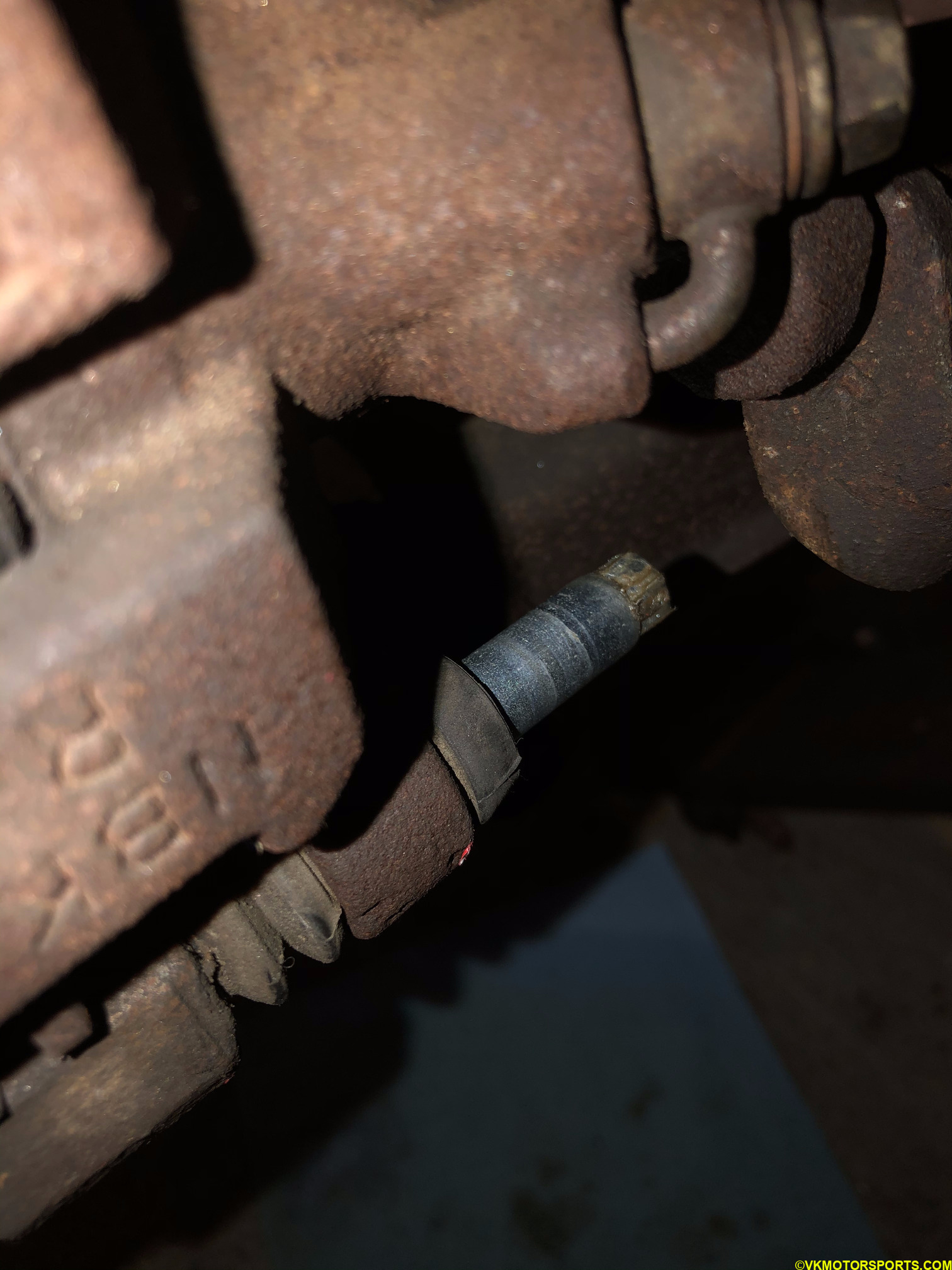 Figure 36. Pull the nut out
Step 6: Now lift the caliper upwards as in Figure 37 and slide it out of the caliper bracket that is attached to the rotor, as in Figure 38. Figure 39 shows the caliper in my hand while the caliper bracket is still attached to the rotor. Place the caliper on the side, such as on a control arm or on a bucket, in such a way that the brake line does not get stressed.
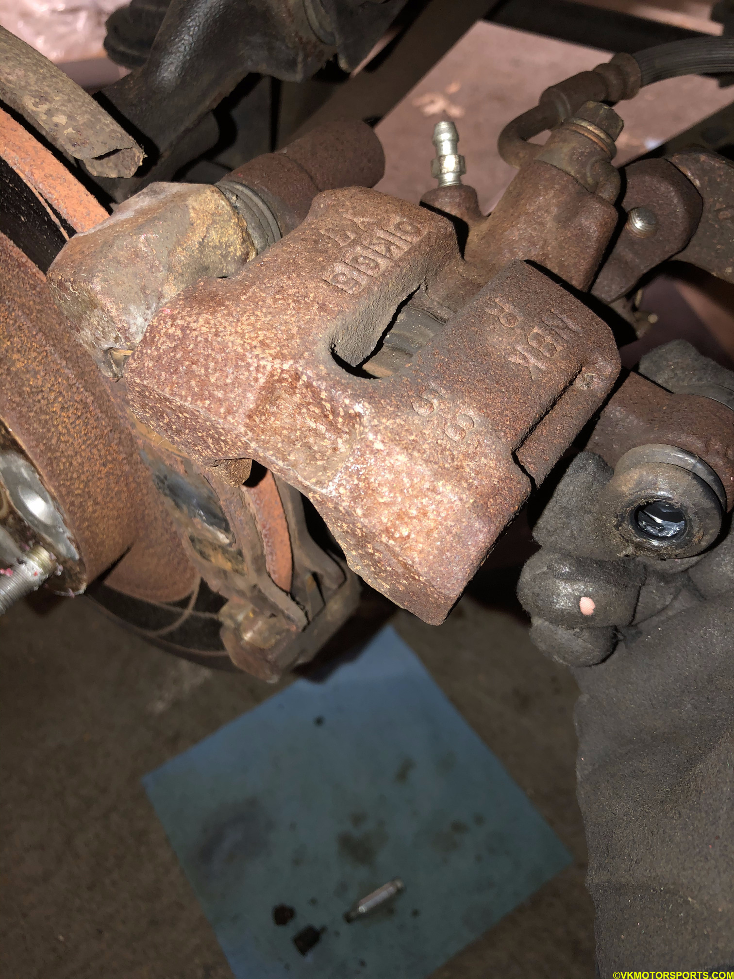 Figure 37. Lift the caliper upward
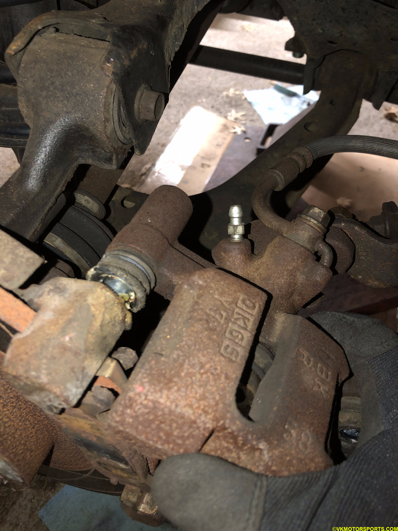 Figure 38. Slide the caliper out
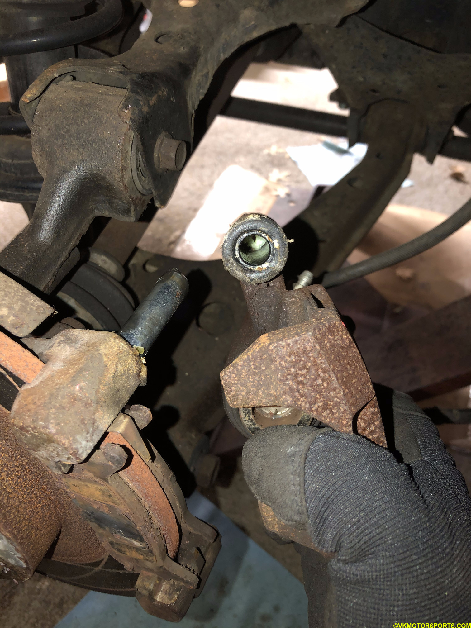 Figure 39. Caliper has been removed from the slide pin
Step 7: Remove the brake pads that are still on the bracket as seen in Figure 40 and you should see the caliper bracket attached as in Figure 41. Figure 42 shows the same view on the rear passenger side of the car with the above steps repeated.
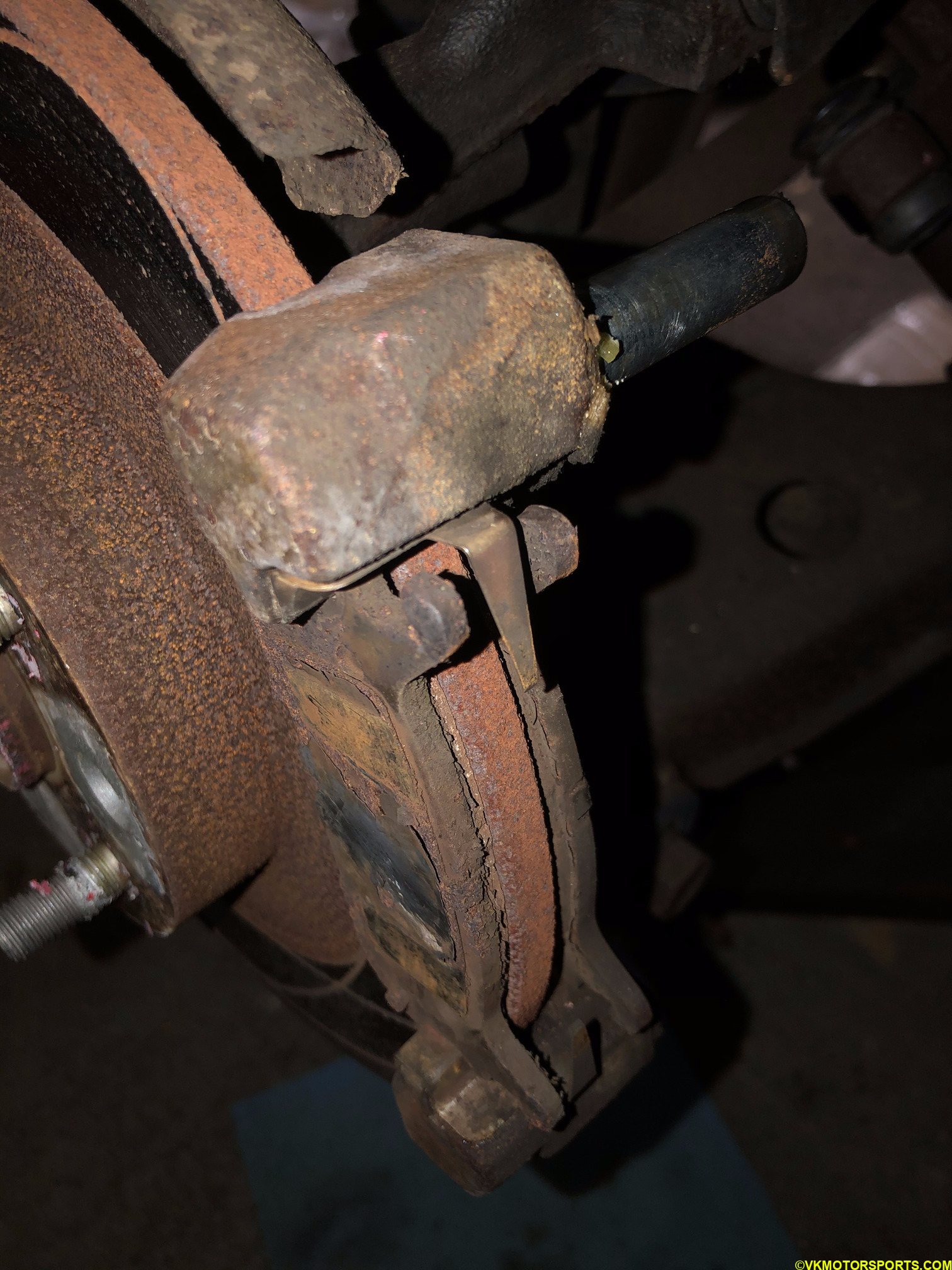 Figure 40. Remove the brake pads that are on the caliper bracket
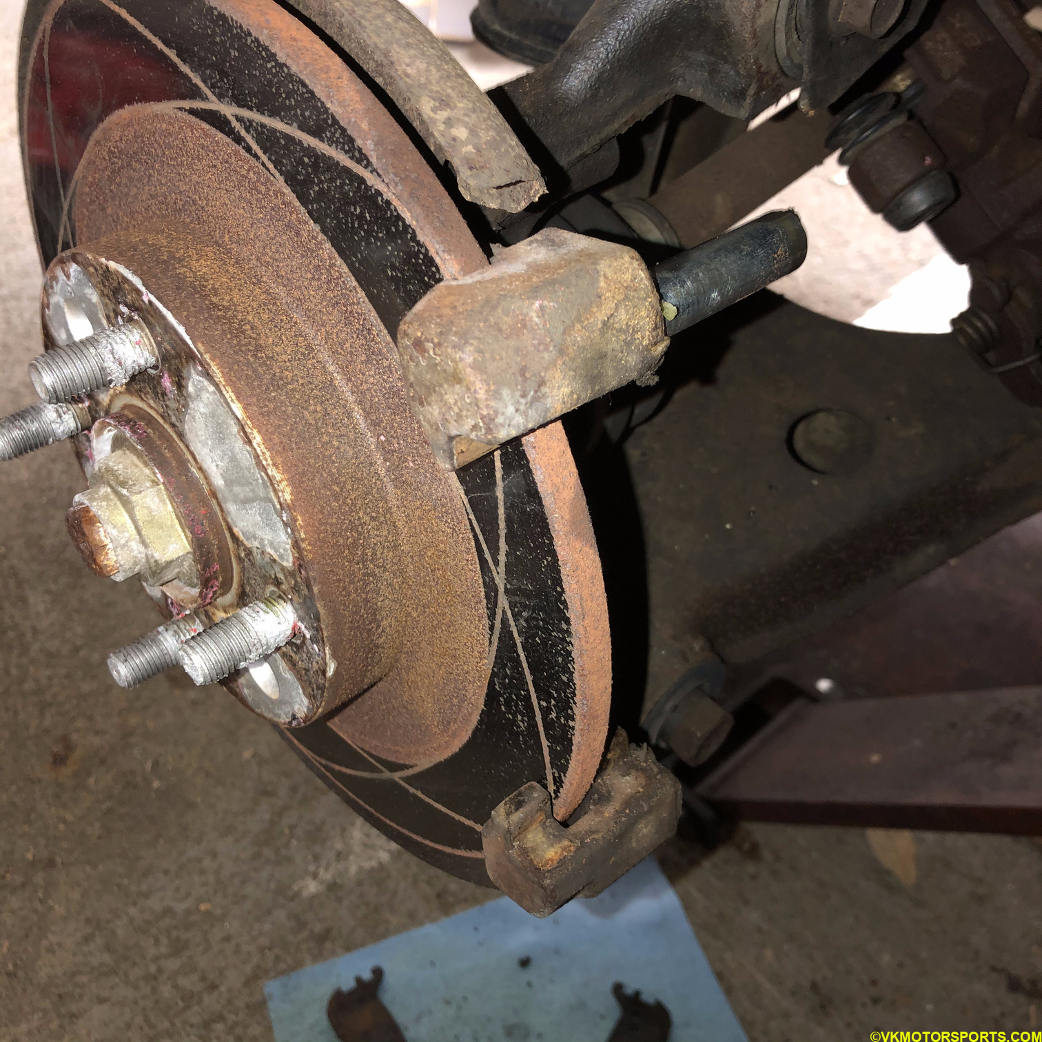 Figure 41. Brake pads removed
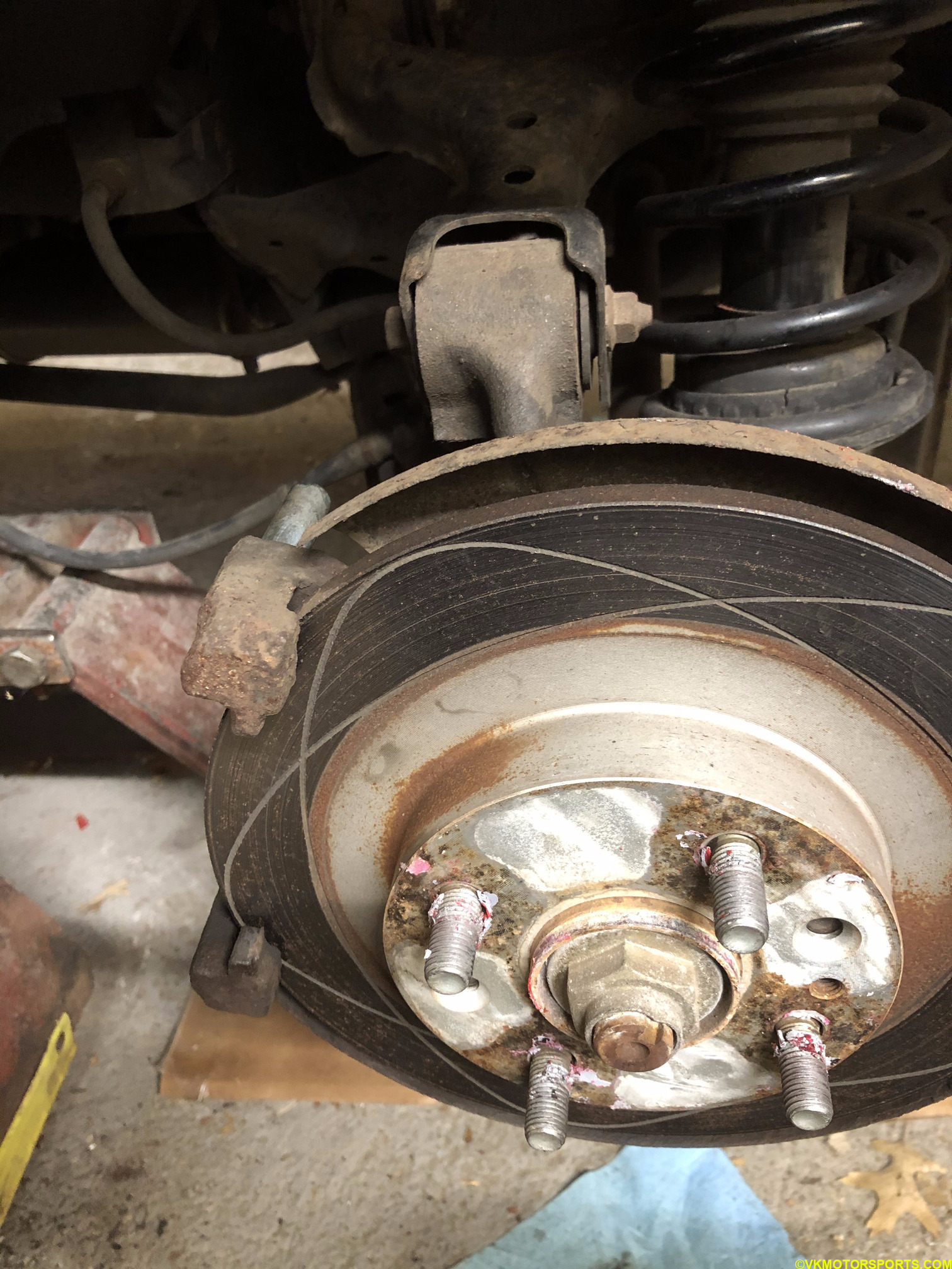 Figure 42. Repeat the same procedure on the passenger side
Step 8: Now it is time to remove the caliper bracket by loosening the nuts behind the slider pin. In Figure 43 it is the nut that is a few inches left of the slider pin, above the tie rod. I had to use a breaker bar, as seen in Figure 44, to loosen the nut. Figure 45 shows the nut is becoming loose while still being on a long socket. If your bracket nuts are too rusty, like mine were, I recommend using PB Blaster and spraying the nuts for a few minutes before trying this. Once the bracket is removed, you will need to take out the rotor. It is a good time to replace it.
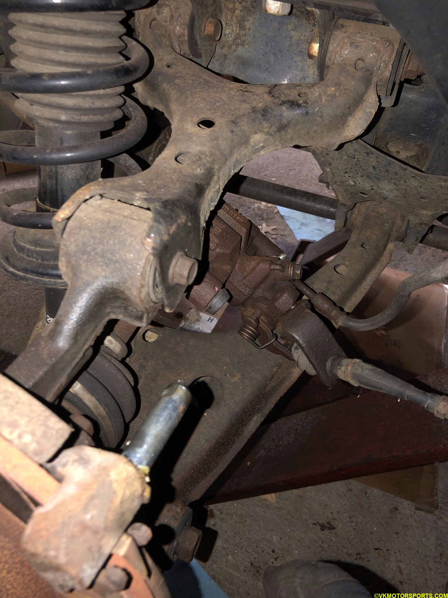 Figure 43. Caliper brake nut is located left of the slider pin
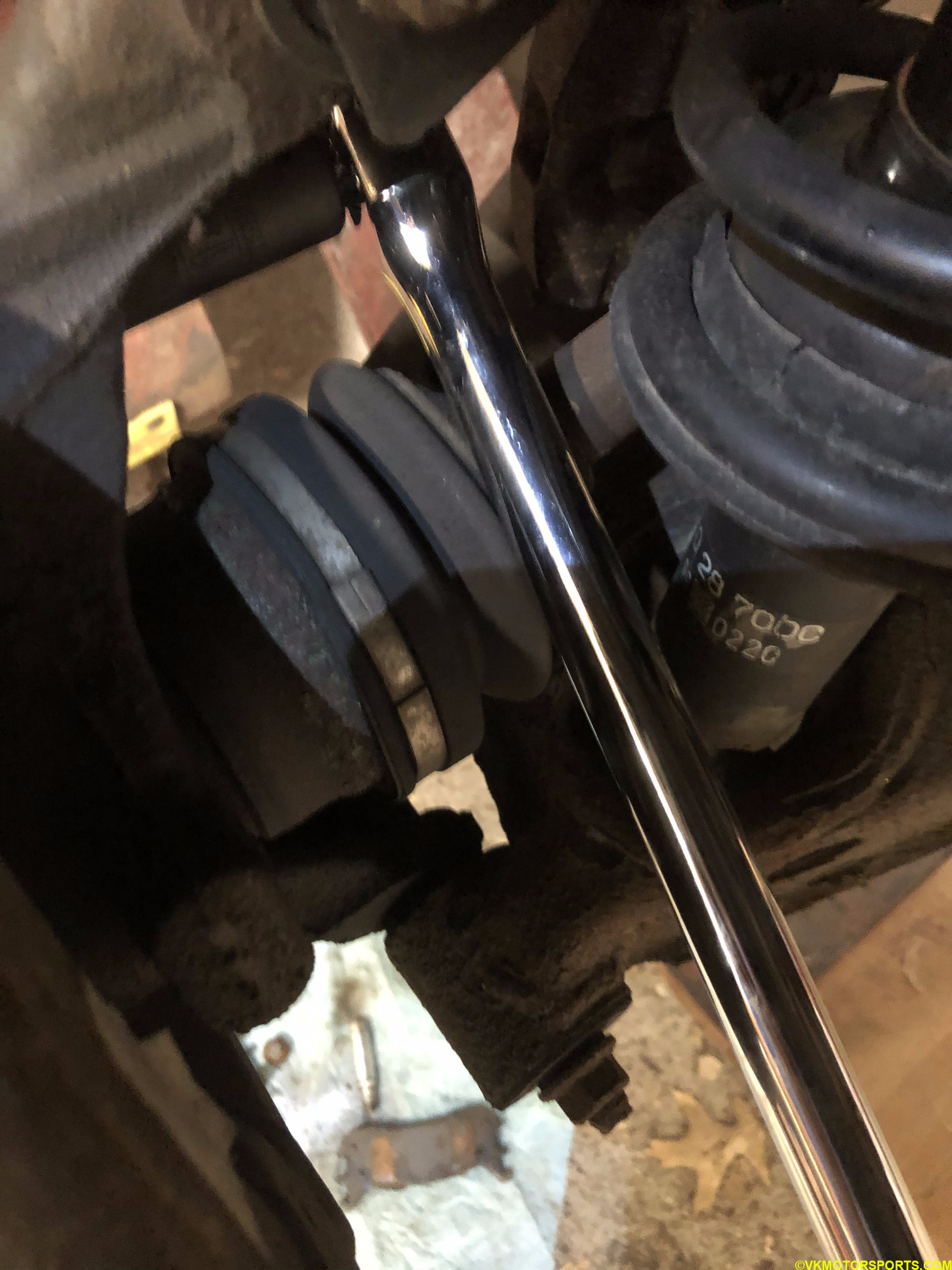 Figure 44. Using a breaker bar to break loose the nuts
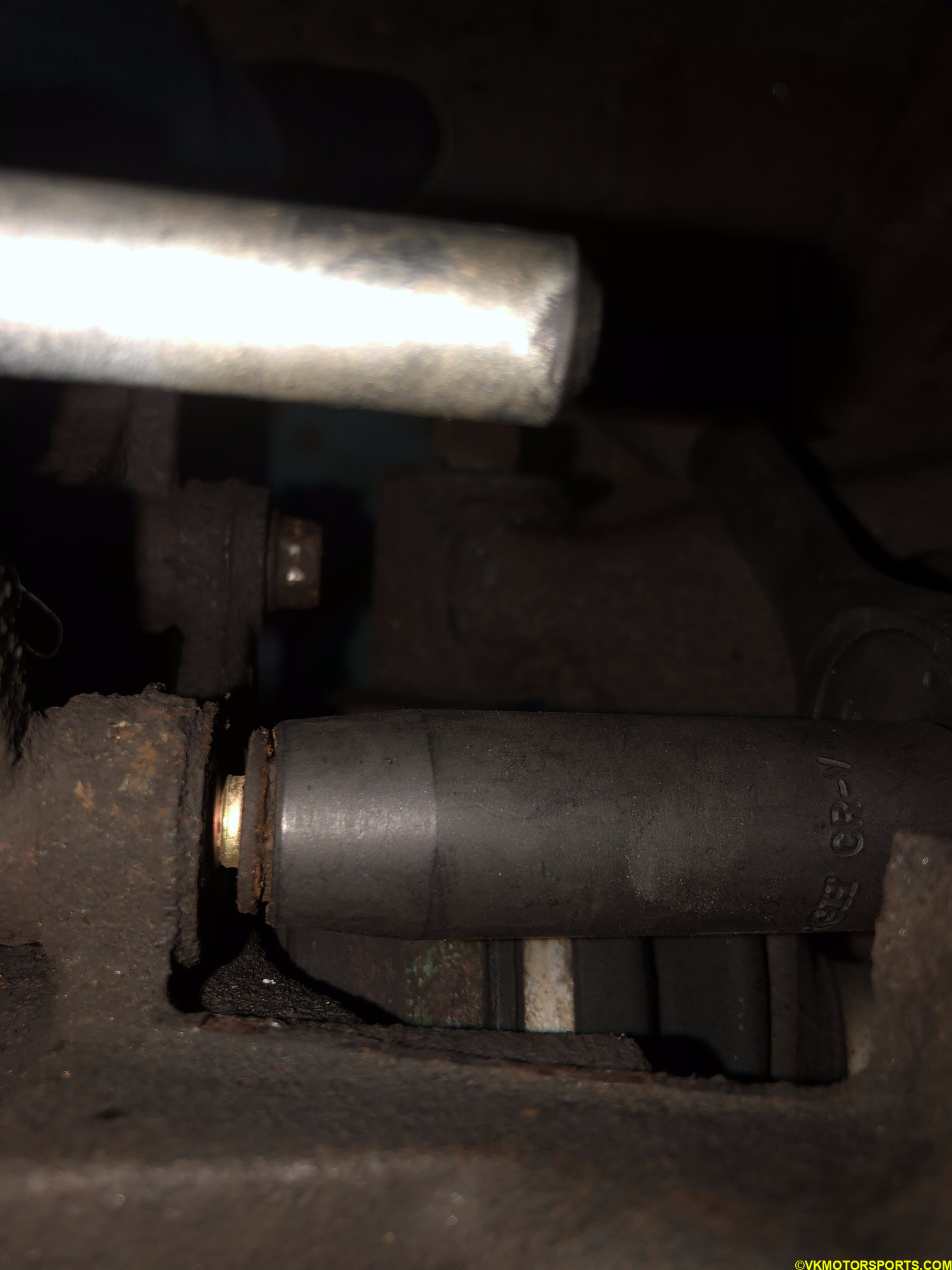 Figure 45. Nut is getting loose
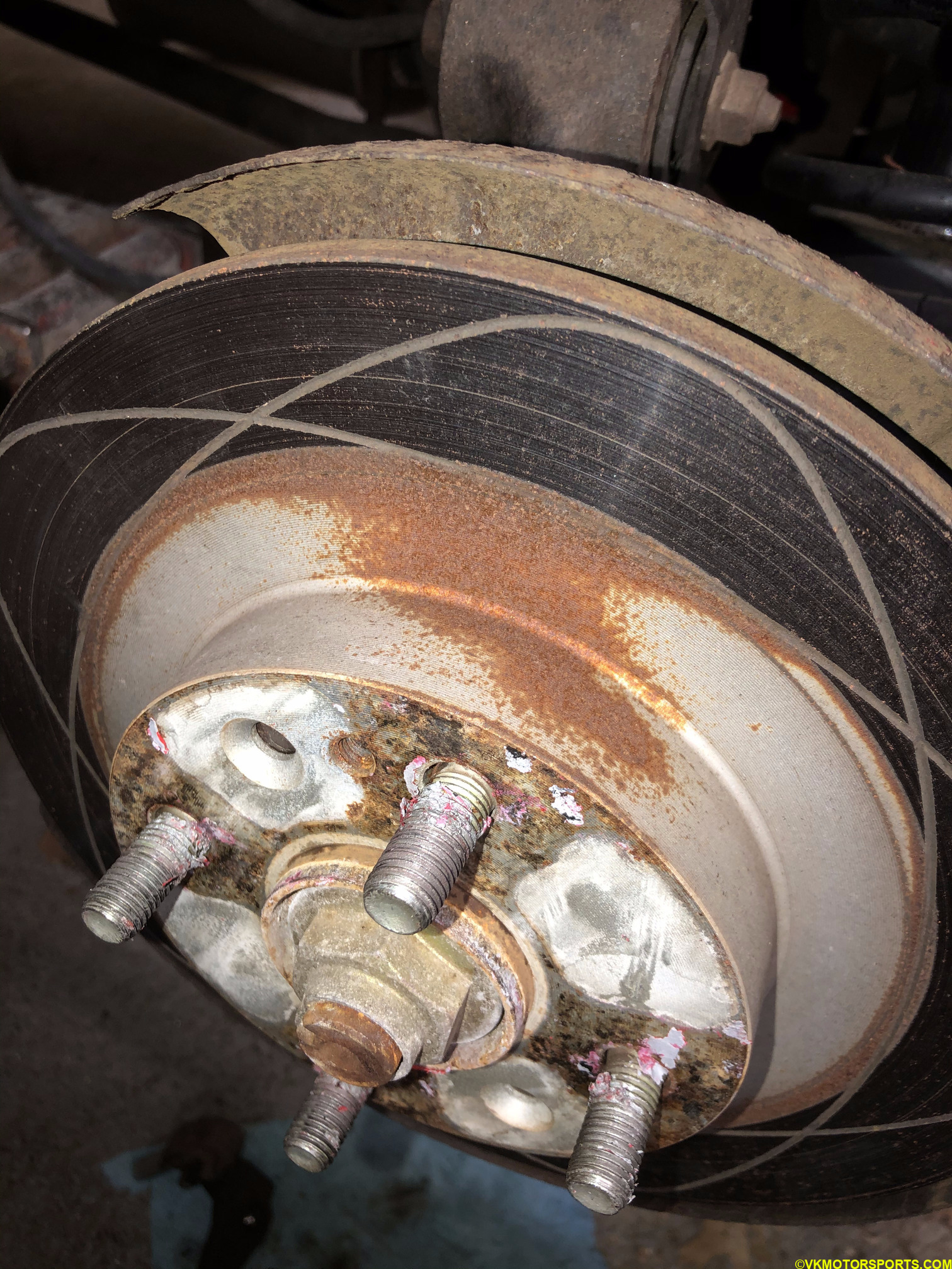 Figure 46. The bracket has now been removed leaving the rotor bare
Step 9: Now we want to remove the rotor and replace it a new one. Since the rotor in my car is probably a decade old, it was stuck on. So you use a matching bolt that fits into the off-center smaller hole in the rotor. Once you tighten that bolt, the rotor will start moving out of its place making it easy to remove. Figure 47 shows the bolt inserted, and Figure 48 shows the rotor has been removed. You can now see the wheel hub.
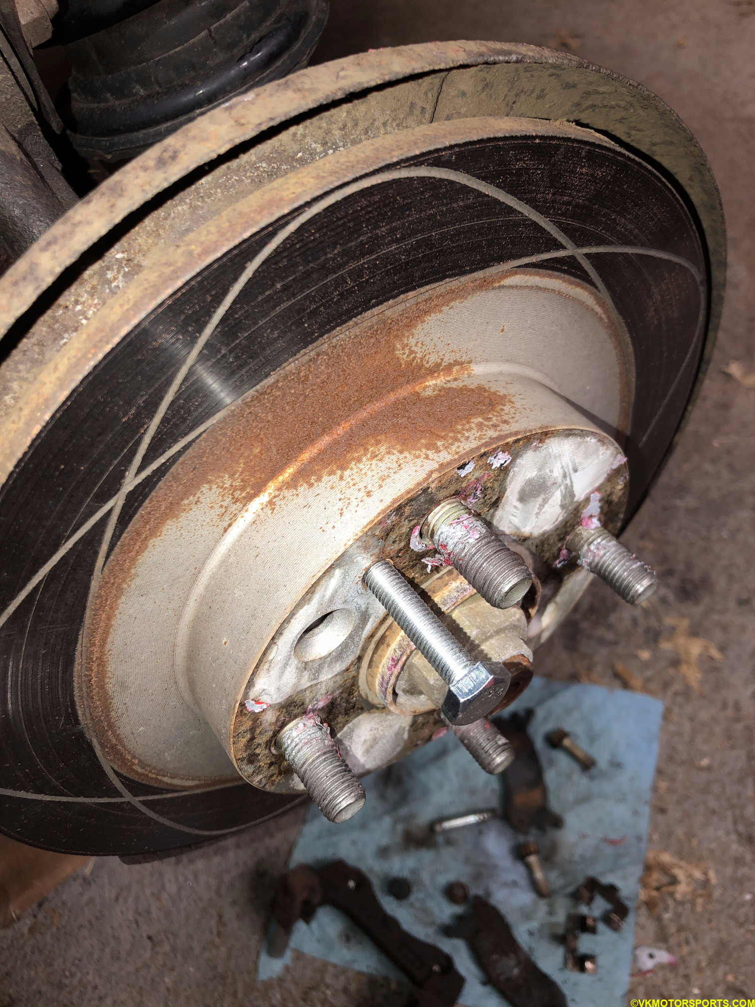 Figure 47. Add bolt to the off-center smaller hole.
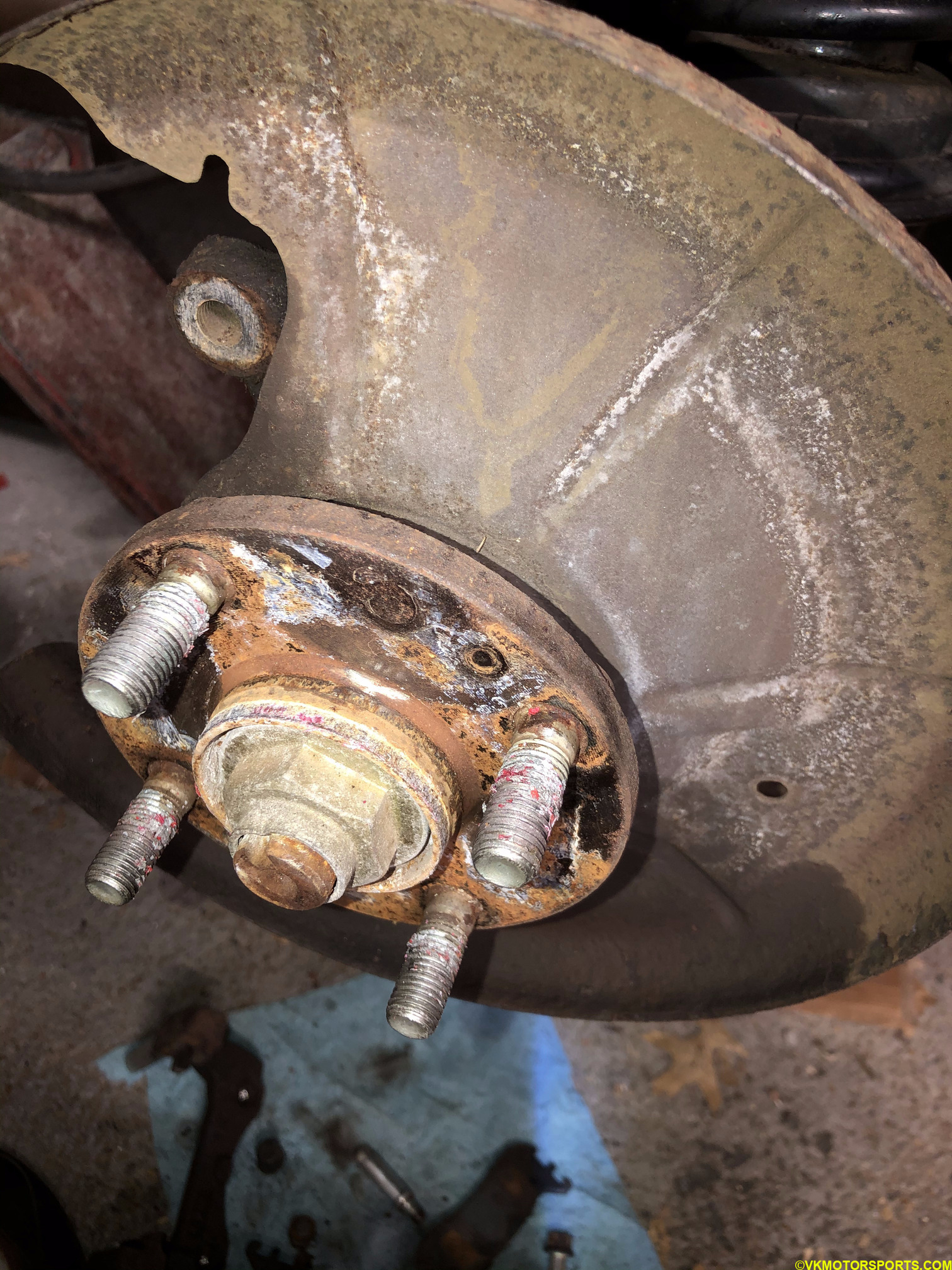 Figure 48. The rotor has been removed, exposing the wheel hub.
At this point you should have all the parts removed and be ready to install te new caliper.
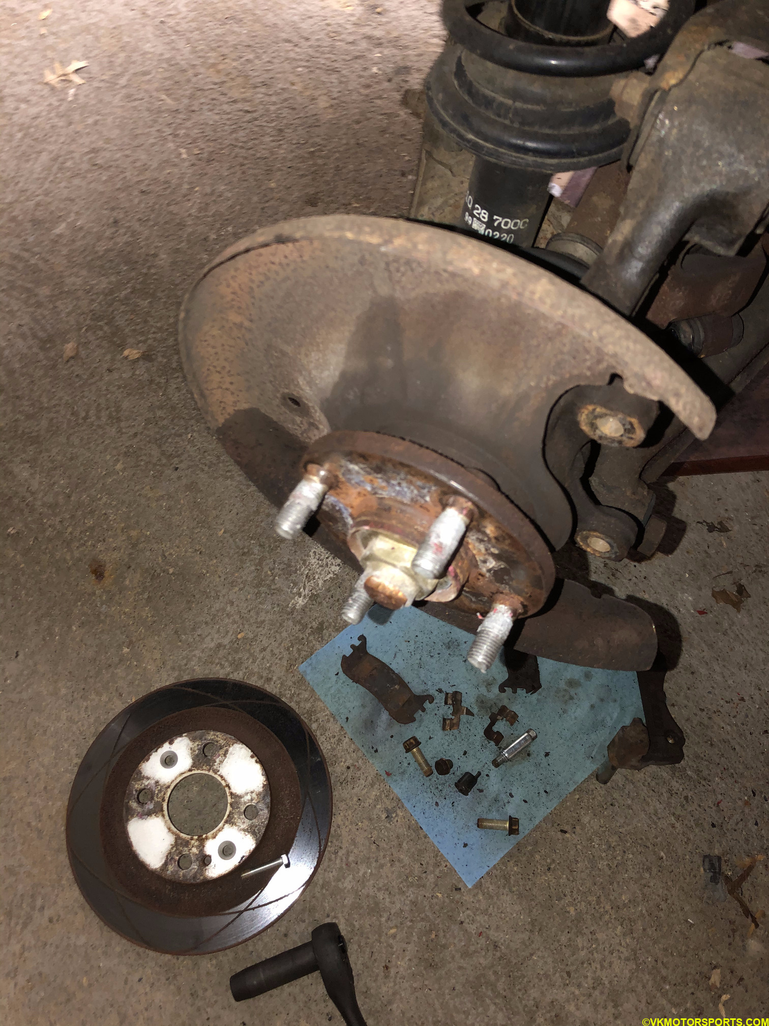 Figure 49. All the parts are now removed, and new ones ready to be installed
Step 10: Take a new rotor from the box (Figure 50) and install it on the wheel hub. Add 2 lug nuts to hold it in place as shown in Figure 51. This is needed so that you can install the caliper without the rotor moving out of place. Notice that the rear rotor is thinner than the front rotor and has one disc rather than two in the front rotor.
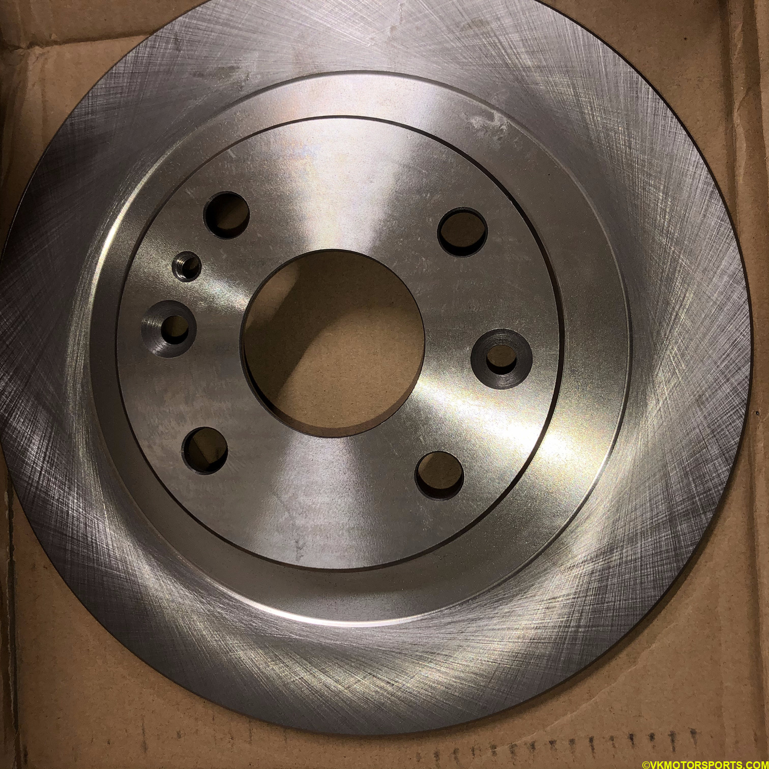 Figure 50. New rotor in box
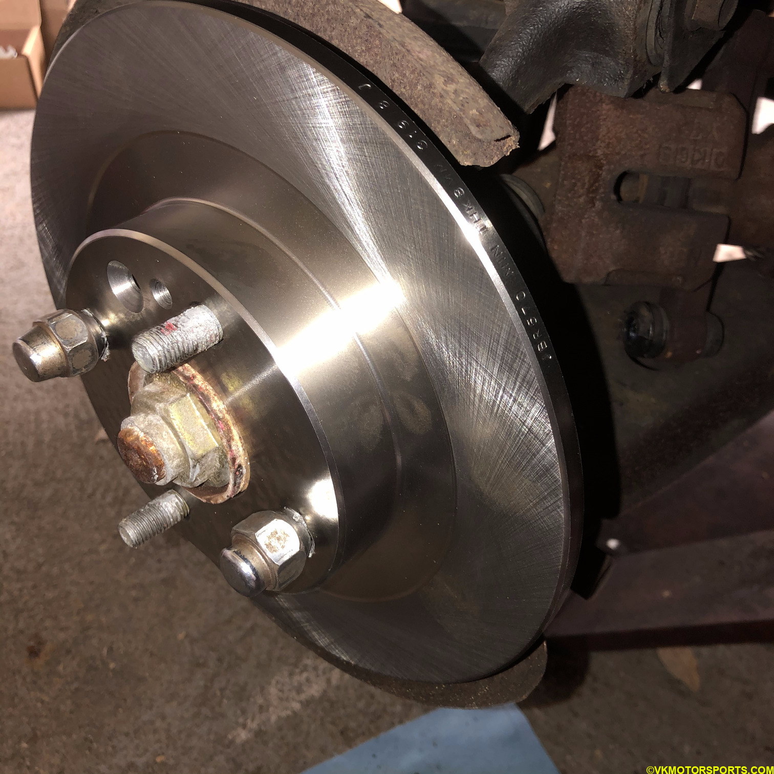 Figure 51. Place new rotor on the wheel hub and hold it in place with 2 lug nuts
Step 11: Apply medium strength thread locker, shown in Figure 52, to all the old caliper bolts that we had taken out in the earlier steps (Figure 53).
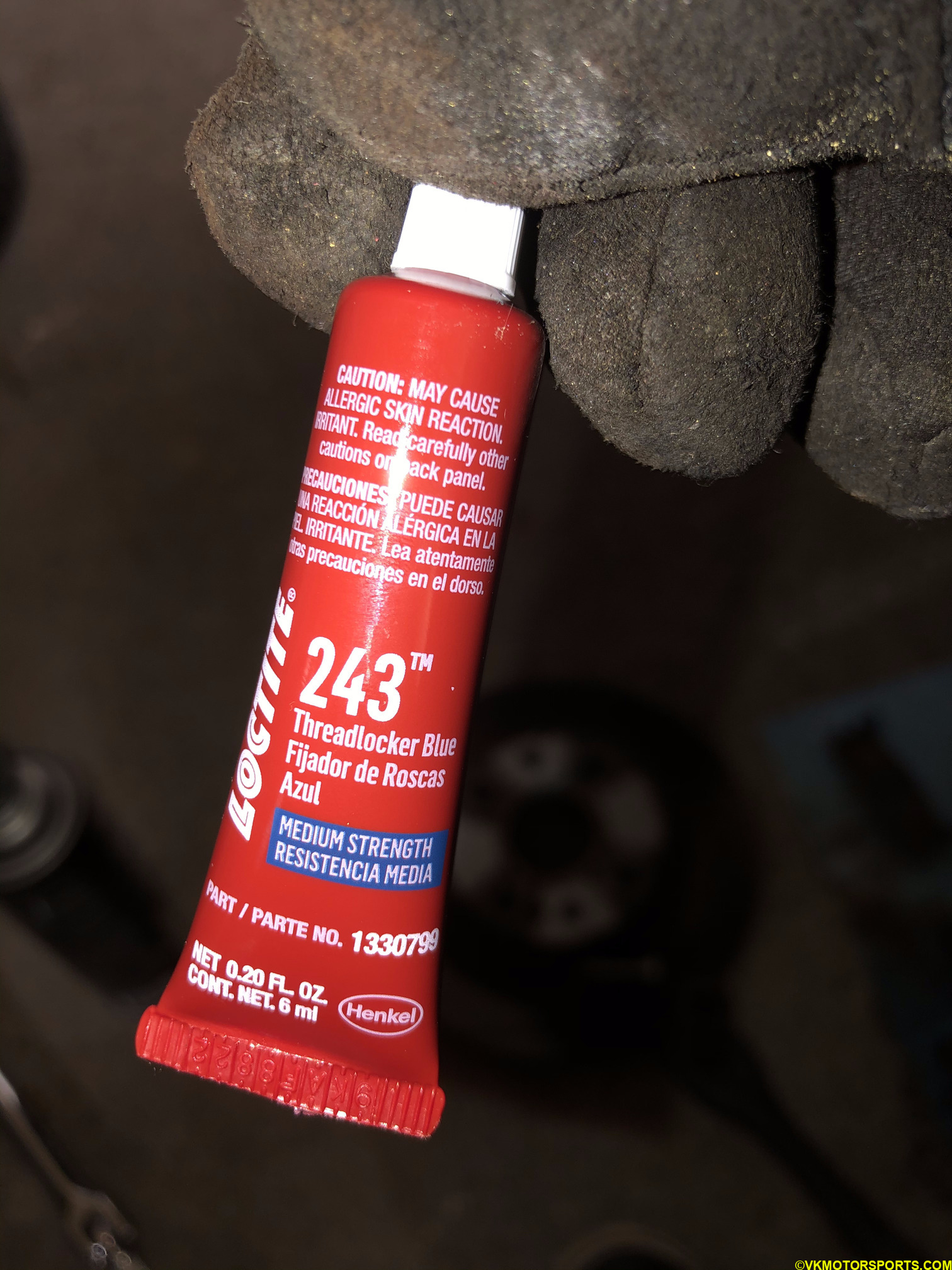 Figure 52. Medium strength thread locker
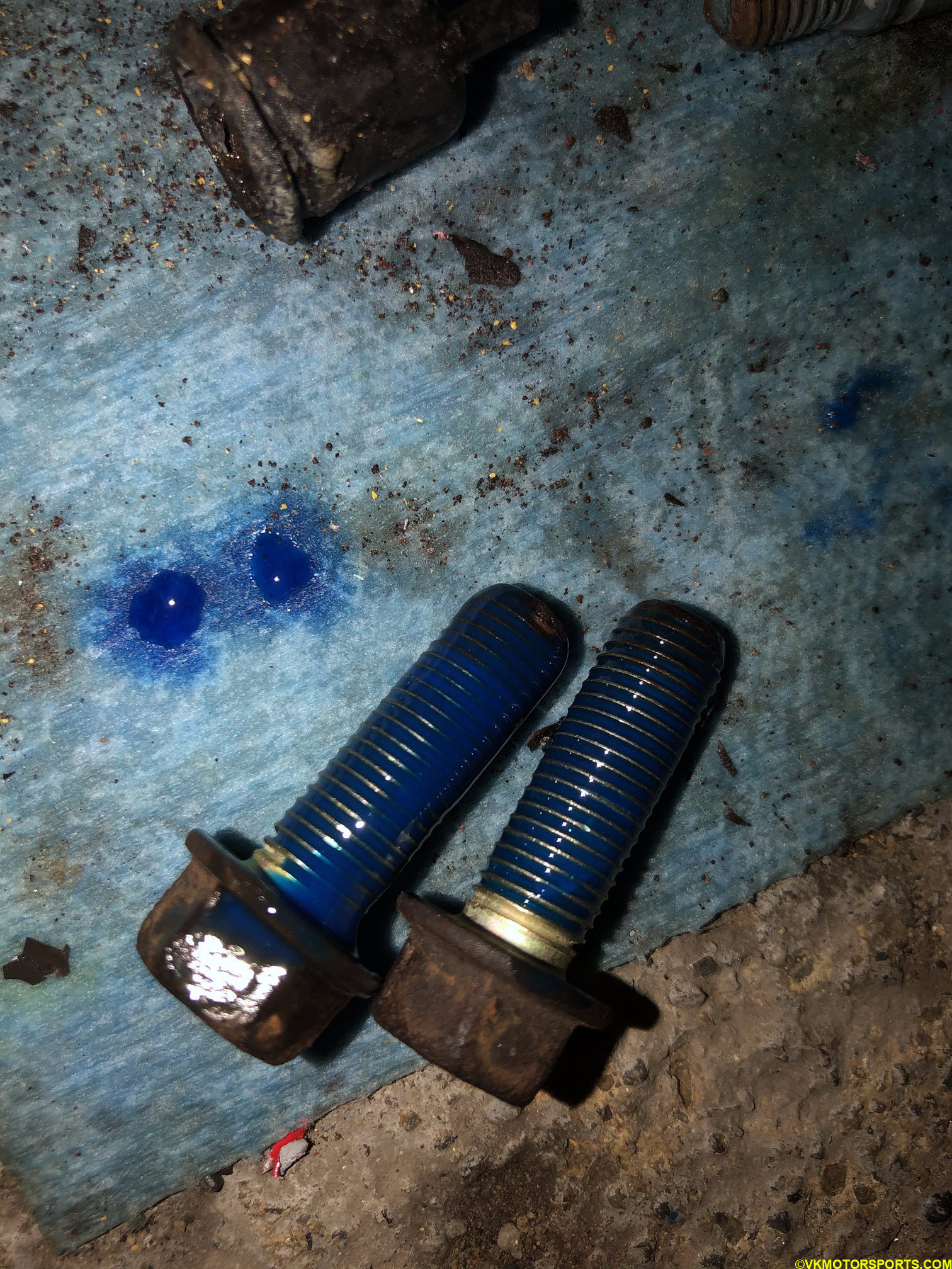 Figure 53. Apply threadlocker to all the bolts
Step 12: Figure 54 shows me using the thread locker covered bolts to install the new caliper bracket to the rotor frame. In Figure 55a and 55b, the process to attach the rest of the caliper is exactly the reverse of the caliper removal as shown in the above steps.
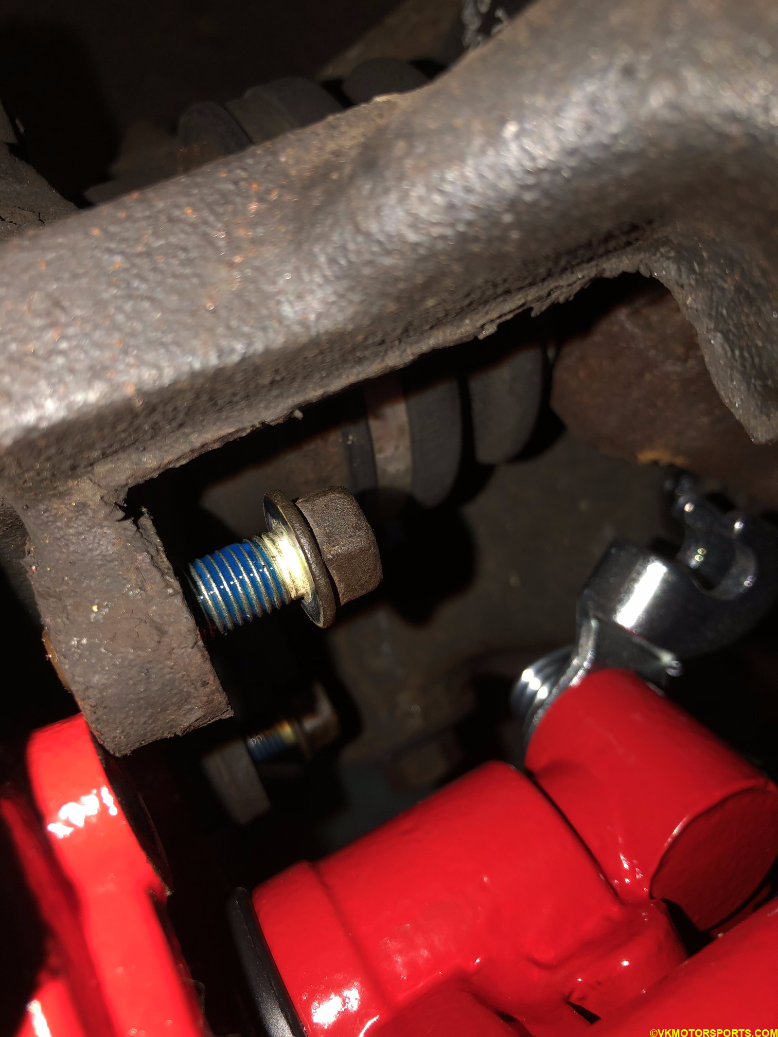 Figure 54. Attach the caliper bracket first
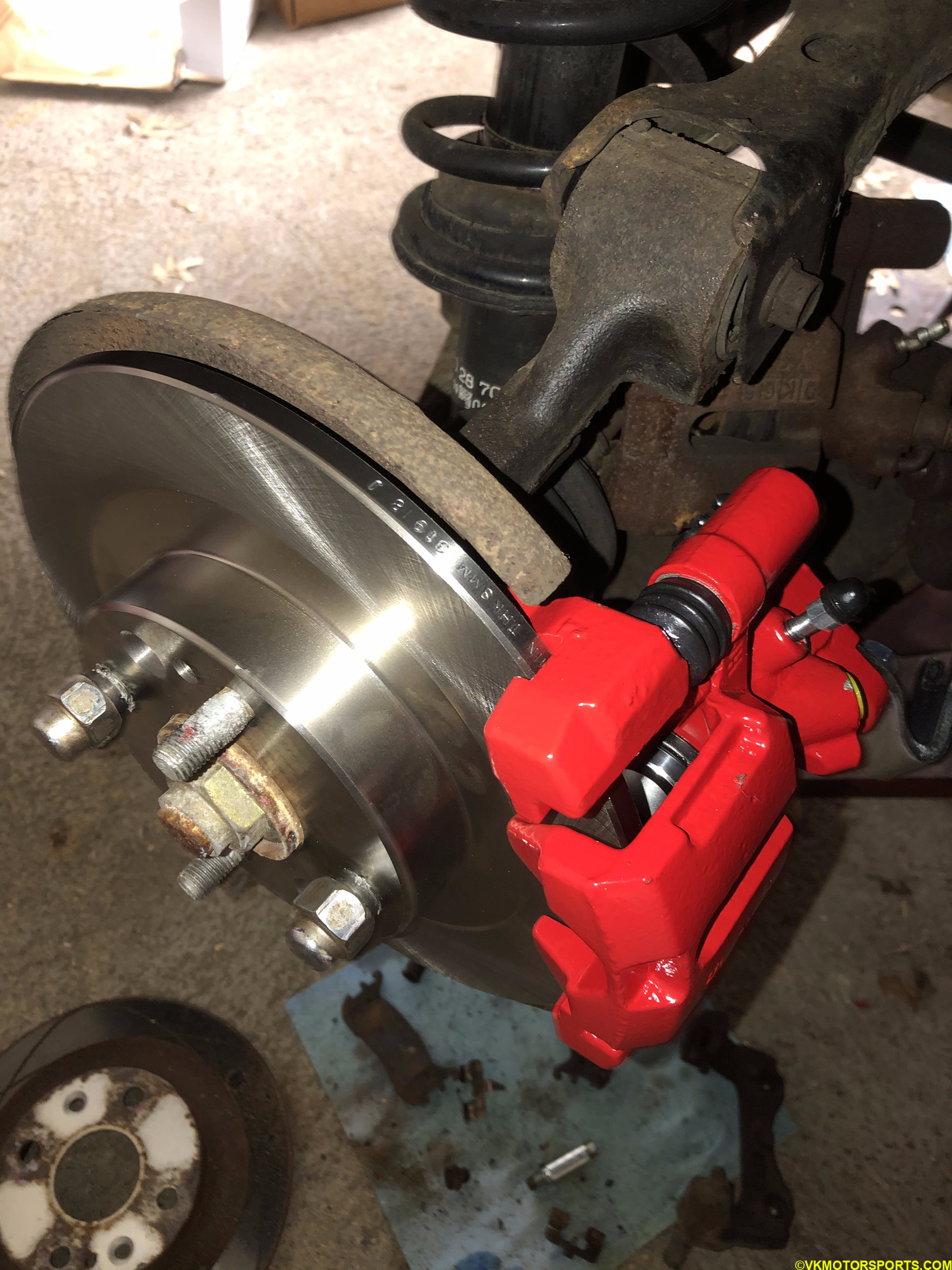 Figure 55a. Driver side view of the newly installed caliper
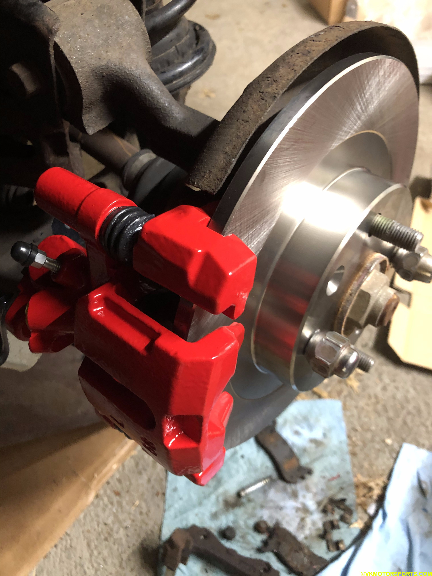 Figure 55b. Passenger side view of the newly installed caliper
Now that the calipers and rotors have been installed, we need to install the brake pads and bleed the brakes as described in the next post.
We need to do that before we torque the bolts to specifications.